|
|
 |
| The Original |
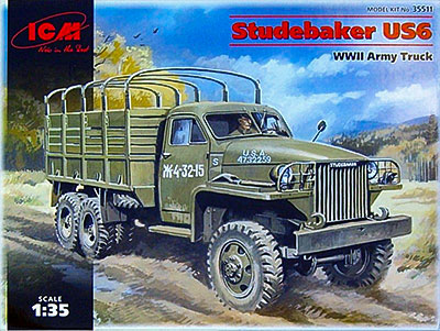
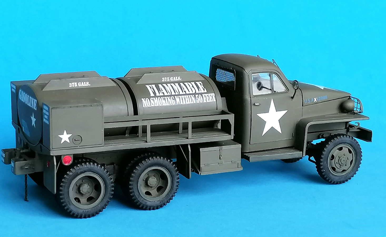
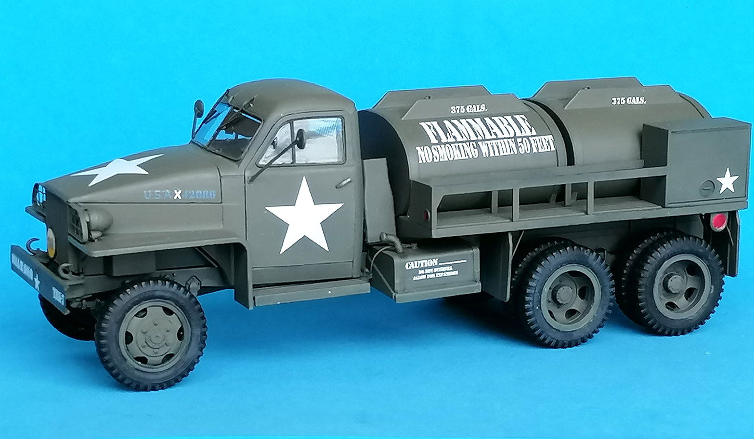
In 1941, the US Government realized that General Motors, the sole producer of 2.5 ton military trucks at the time, would not be able to supply the number of vehicles necessary for the US Army, Navy, and Marines, let alone the deliveries promised to the Allies in the Lend-Lease program. This led to Studebaker and International Harvester being included in the war effort, who both developed their own 2.5 ton trucks to the same specifications that GMC had met with their CCKW 353. To keep supply lines simple, it was decided that GMC would mobilize the Army, IH the Navy and Marines, while Studebaker would come up with the trucks for export (and for the Alaska-Canada Highway). Studebaker's US6 model was built in much the same variants as the "Jimmy", i.e. with short and long wheelbase, with and without winch, with closed and open cab, and in numerous special versions. One of these was the 750 gal. gasoline tanker US6 U5, which carried a tank installation made by the Heil company, like the one for its GMC "cousin".
| The kit |
Having tried to build the Hobby Boss CCKW 353 fuel tanker model and finding it definitely inadequate (https://panzer-modell.de/berichte/studebaker_us6/studer_e.php), I had replaced HB's truck with an ICM Studebaker (#35511), and now I wondered how ICM's tanker kit would compare. It has sprues A and C from their original cargo truck kits, with a new B sprue containing the cab and hood parts, and sprues D and 2x E for the tanker details; sprue F gives the clear parts in a new arrangement. All new sprues show parts numbers, whereas the old ones come unchanged without these, so I recommend to make xerox copies of the respective instructions parts to avoid constant leafing through them (and don't believe what they say about parts A25,26 and 4x64, the running boards and their braces – they ARE needed!). Besides, these older sprues show their age, not only by the wear of the molds but also because of mistakes made in designing them: On some parts, the connections to the sprue go over into positioning pins, like on engine half A32 and (four!) on radiator A24, so beware not to "clean" off these. On A6,66,67, on the other hand, the connection goes over into the part and has to be cut off it. Whereas the rear leaf spring packs C3 won't go all the way on the axles without some whittling. – The clear parts come in a new arrangement on sprue F, but still with the same problem as before: Headlight bodies A10 have a mold seam that looks like the separation for a lens rim, and clear parts F1 have a lens ring, too, with a rear extension that fits into A10's ring. Which leaves you with a very long light plus the task of painting the lens ring on the clear part. – The decal sheet gives markings for two trucks in US Army service: one of the 101st airborne division with an interesting registration number of a Reverse Lend-Lease vehicle, and one of the 2nd armored division.
| The build |
On sprue D, ICM has added new lateral frame rails w/o the spare wheel carrier release mechanism. Cutting the pintle spring out of part A7 is difficult – I recommend to just completely cut off and install the "V" braces, never mind the central part which won't be visible anyway. The ladder frame was easy to construct, only with braces A63 and A76 did I have to whittle the positioning marks a little, and the rail extensions A59,60 that hold the front bumper didn't have the locating pins shown in the instructions, which made mounting them a little difficult. And the positioning half-circle hole for shock absorber A4 on the right is upside down, so the pin on the part has to be cut down for it to be mounted correctly.
 A truck without pintle needs hooks to pull it when necessary.
 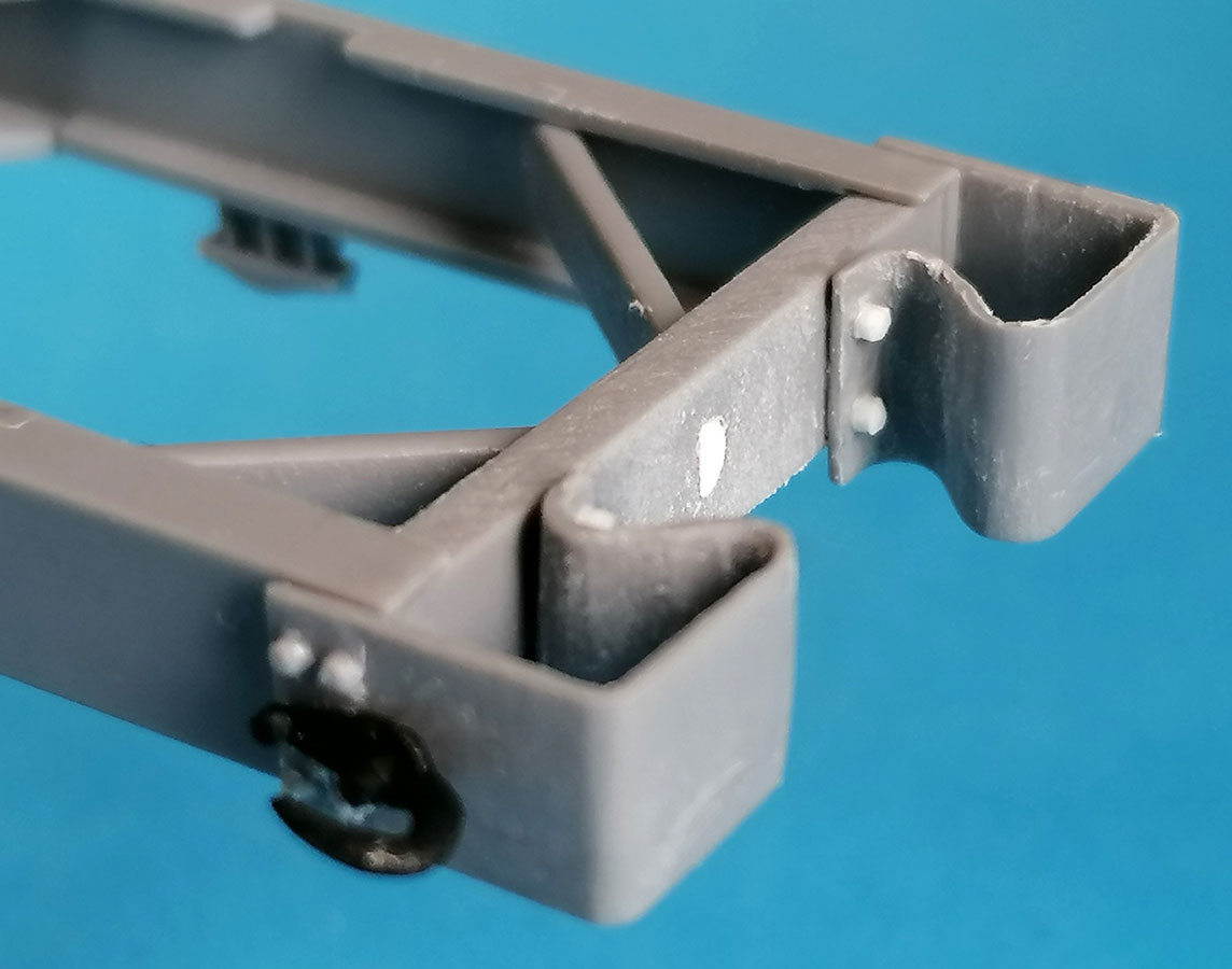 ICM acknowledged that and developed new rear bumperettes with such hooks – but unfortunately they molded straight hooks without the upward bend of the prototypes onto these bumpers, so they're incorrect. I thinned down the original bumperettes A39,40, added nuts to their rear flanges and correct hooks from http//3dptrain.com/. Two more of these replaced the kit items at the front bumper.
The spacer rails D33,34 are fastened on the chassis rails with U-bolts E21. Interestingly, ICM seems to think that one of these on either side should suffice, whereas HB's kit gives four. I think that HB's version is more realistic, so I scratchbuilt 6 more from 0.5mm rod and 0.5 x 2mm strip and installed them according to HB's scheme. (I later replaced the outward facing vertical parts of E21, as they were noticeably thicker.)
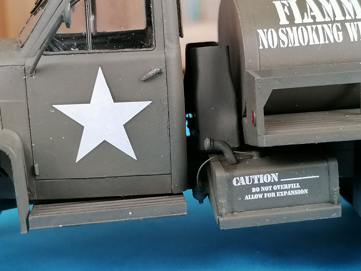
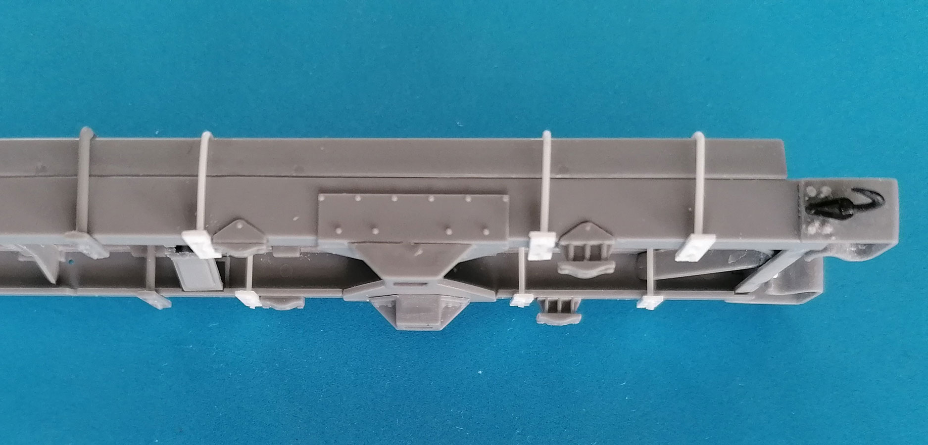 The chassis fuel tank received an outlet for the fuel gauge wire and the fuel line, both from wire. Tank and stowage box have been redone and now come on sprue D, but without improvements; I should've sanded off their triangular supports and scratchbuilt new ones, as I had done on my first Studer.
The main parts of the motor block suffer from some mold shift – not badly, but enough to mount part A29, the flywheel housing, at an angle, so check the engine's fit in the chassis before the glue has set. I added an oil sump drain nut. The cylinder head is very detailed and begs for some more add-ons, but as without hinge representations, the hood can't be built open, I found that a moot option. Which also goes for the ancillary parts that get added around the engine – nice to have and know they're there, but hardly ever visible.
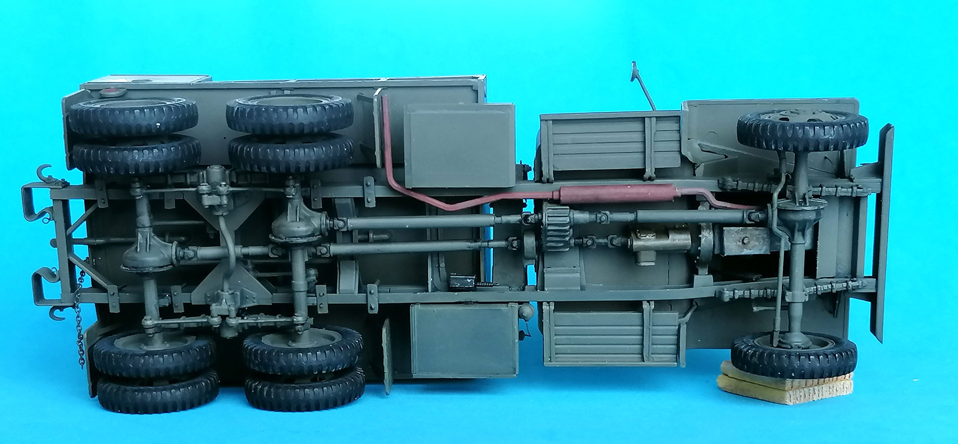
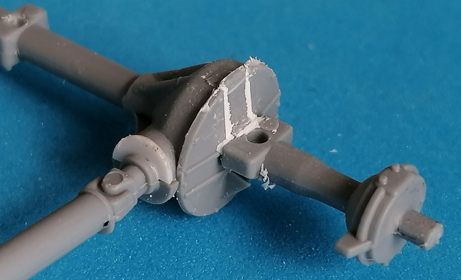 The drive train base is one piece, containing the three axles, their drive shafts and one half of the respective transfer cases. Good idea to facilitate the build, but the parts necessary for the completion of the differentials are very badly fitting – and that's not (only) due to the age of the mold, but to sloppy original mold design. It takes a lot of work and putty to get this area presentable. True, most of these deficiencies are on the top side where they're not very obvious, but still, this is a point of basic kit design. The front axle can not be built steerable (by me).
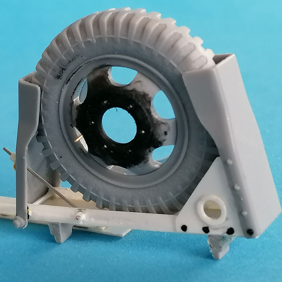
The wheels bear the "Firestone" logo and tire size markings, but only on the sides that face outwards; watch this when placing the spare wheel in its carrier. I added 0.3mm brass wire valve stems to all wheels. The spare wheel rim should have all of its bolt holes drilled through and the nuts removed – it just stands in its carrier and isn't bolted there; purists might thin the rim center for more realism. If you want to build the other wheels turning, cut down the pushout pins in the wheel rims so they won't rub on parts C9. And for the front wheels, paint the outward facing side of C9 dark, as it will be visible through the rims; this also goes for the visible inside areas of C6.
ICM's spare wheel carrier is a lot better than that of the Hobby Boss kit (which is a faulty copy of the improvable sample on Italeri's GM water tanker). Having scratch built the Studer variety for my other model, I looked with a very critical eye and found the parts much too thick for a representation of sheet metal. Granted, you can see very little of the thing between cab and front tank, but the tops of the lateral "clamps" D11,12 stay visible and should be thinned down to a more scale appearance.
 And then AMS got the better of me and I replaced the bottom part D29 with a C-beam from 0.5mm sheet (on transplanted "feet" of the kit part) and 2mm high sides from 0.1mm sheet. The same material was used for replacements of the triangles D30,31 (in the instructions erroneously called E30, 31) with ones that reach up 10mm and bear a "ring" of 3mm outer diameter around their holes. D11,12 had to be widened on their insides to receive the new overlapping parts. Additional "rivets" were made with (blackened) white glue dots. Holes were drilled into the sides of the bottom C to receive L-shaped stabilizing rods from wire, to be "held" by hexhead nuts on the outsides. The details on the outside of D11 are rather correct looking, but to receive the wires, the positioning holes were drilled trough and the outside fixtures replaced with 1mm wide strip plus a nut. To show off all this work, I decided to leave the carrier empty.
ICM have developed a new sprue for the cab – and rightly so, because the original one left a lot to desire, most obviously the corrugation at the roof rear that continues halfway down by the door frames. The new B sprue gives a differently (read: much better) constructed cab floor and has the seam between roof and rear wall just where that corrugation should be – but unfortunately is not.
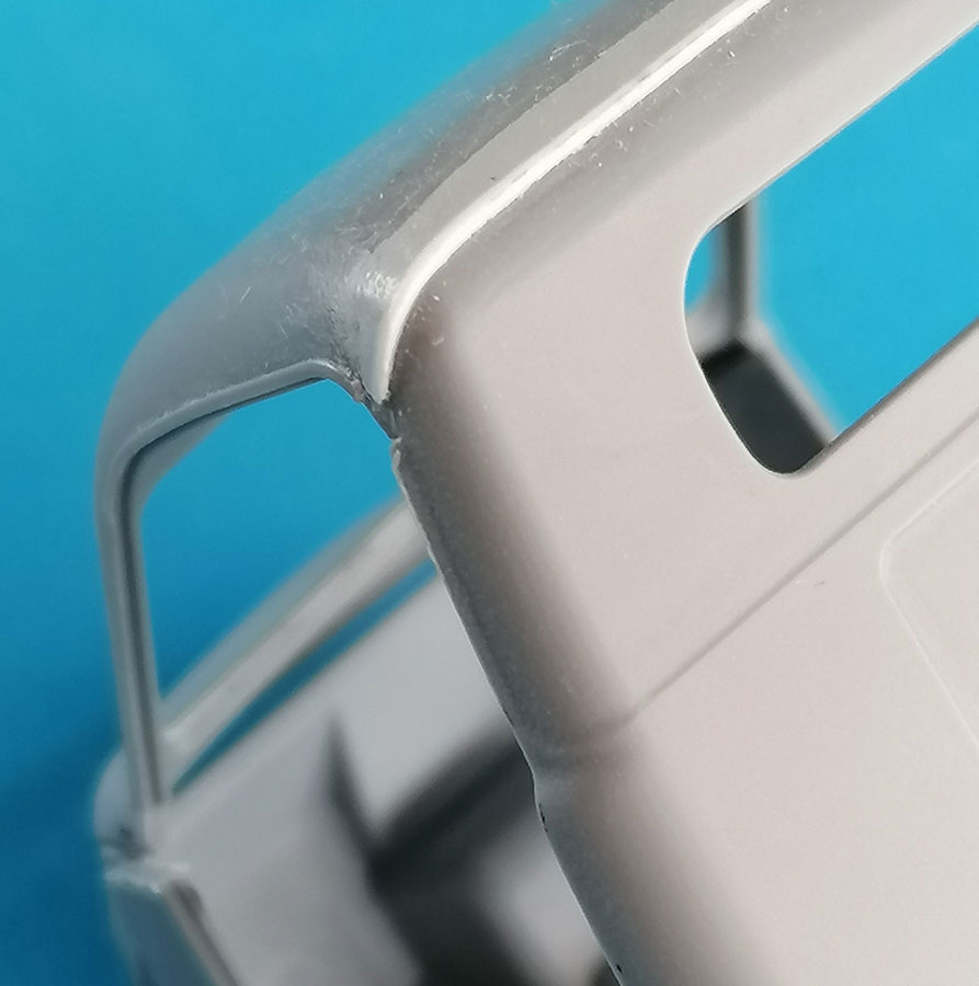 The roof now has rain gutters above the door openings, and the rear wall part shows the continuation of said corrugation along the door frames, but you have to remove the last 1.5mm of the gutters (cut in line with the faint groove at the top of the new doors). This is also where the corrugation on the roof ends: I imitated it by cementing a piece of 0.5x0.5mm plastic strip onto the seam between roof and rear wall that I then faired in towards the front with Mr. Surfacer 500. Which is why I glued roof and rear wall together first, before joining them to the rest.
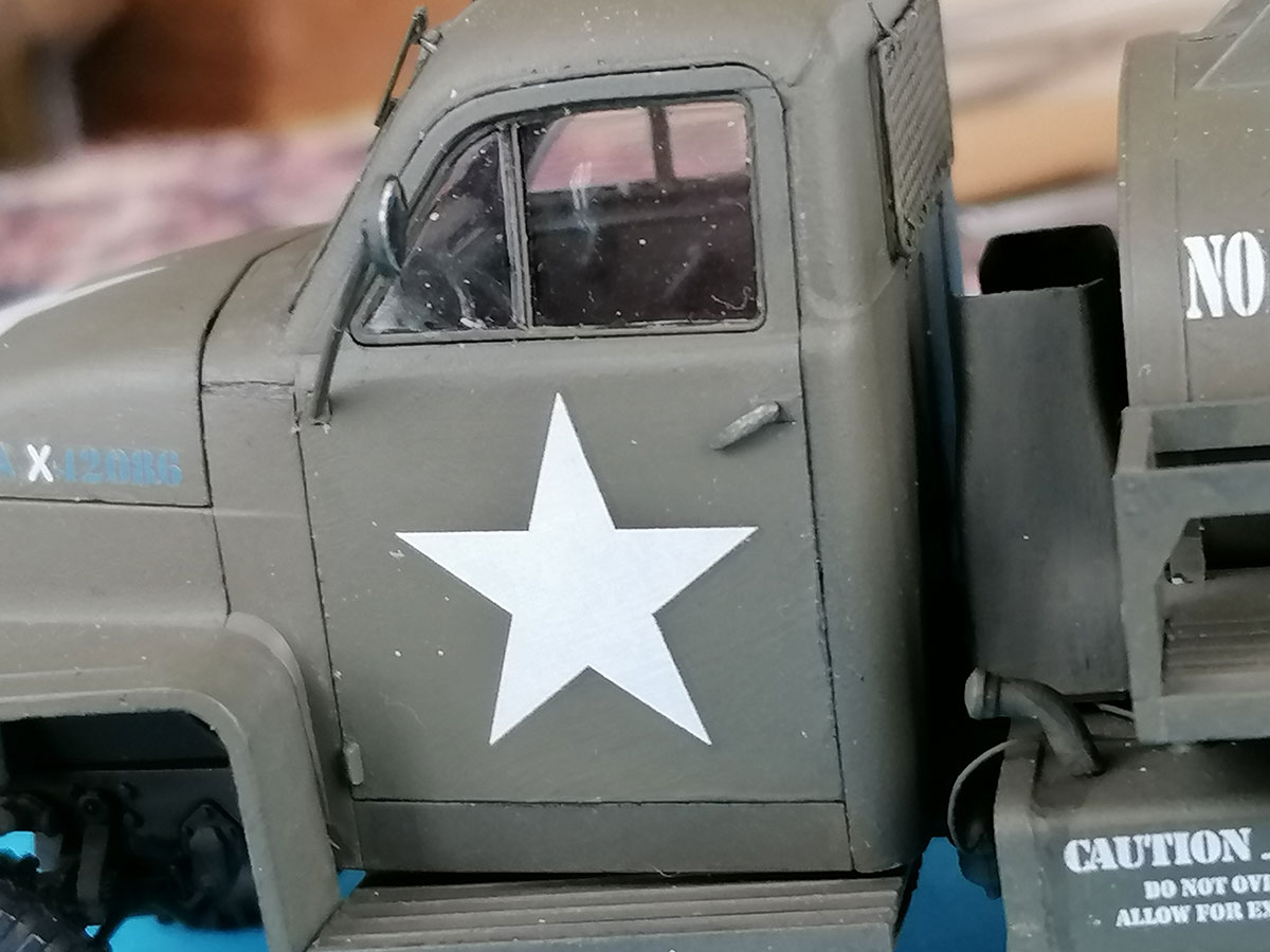
On the prototype, the upper door hinges go into the cowling, but the kit part is not thick enough to install a hinge, so the doors had to be mounted closed. The seats were upholstered by dabbing Tamiya Extra Thin on one layer of a 4-ply paper handkerchief.
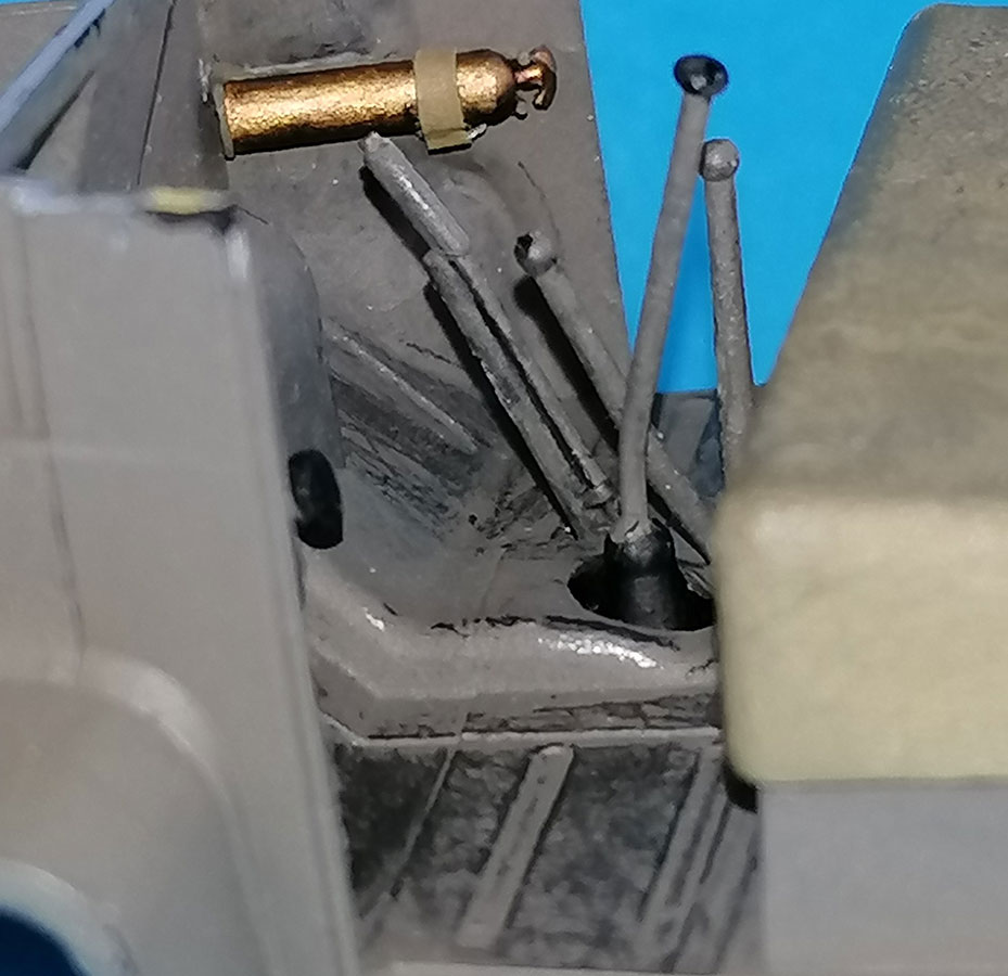 The new steering wheel has grip-knuckles on its underside and a separate horn button. Below the dashboard on the passenger side I installed a scratchbuilt fire extinguisher on the side wall. Of the shift levers, only the gear shift one has a black knob, the others are in vehicle color all over. Clutch and brake pedal treads don't even try to look octagonal any more, but with closed doors, they can't really be seen anyway.
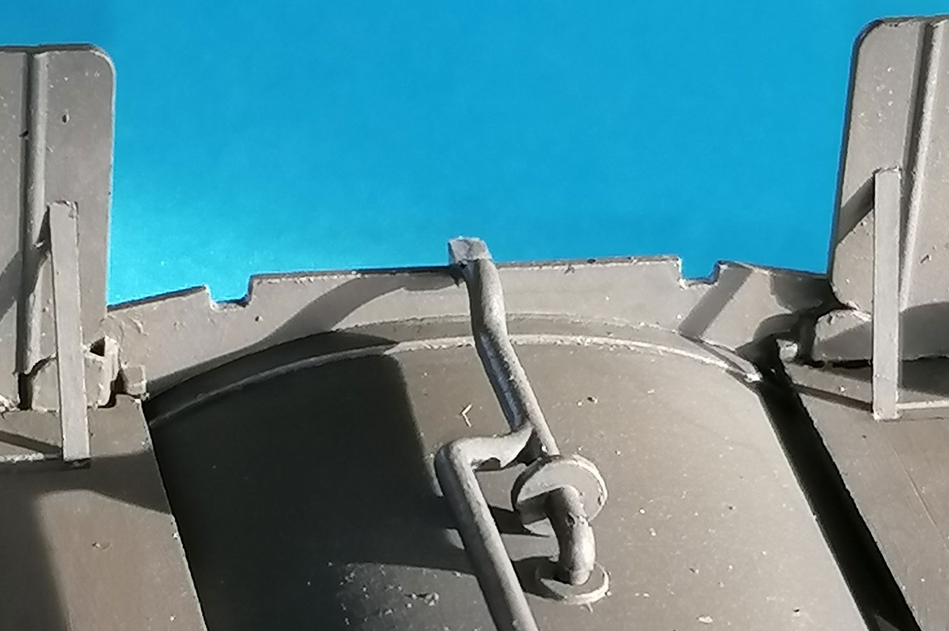
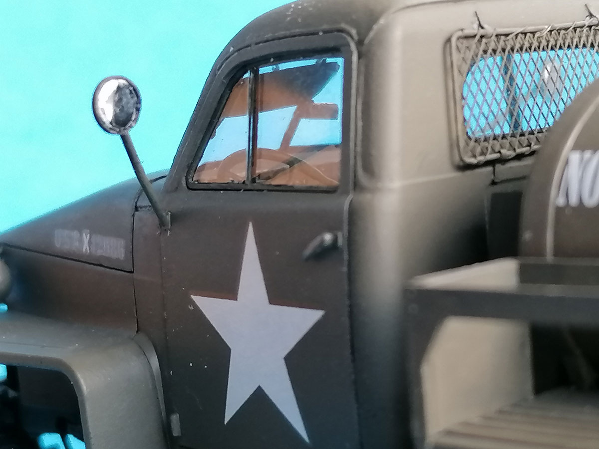
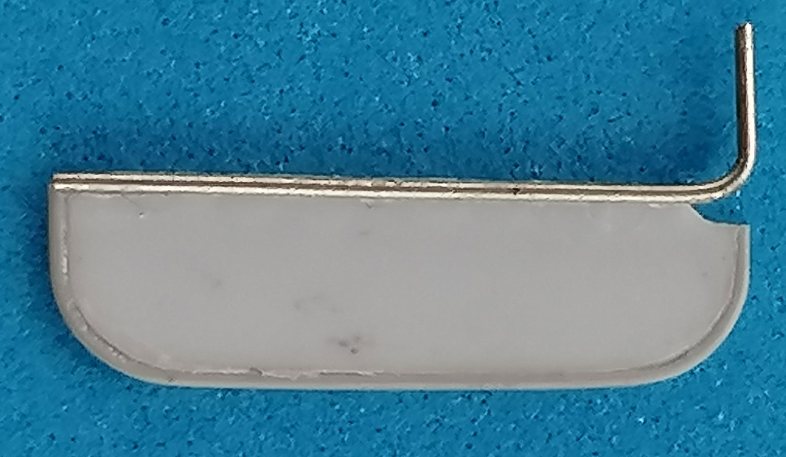 The clear windshield looks good – at first glance. And then you note that it still doesn't have the inside central vertical brace that carries the cab rearview mirror. That mirror is useless with the tanks in the back – but it's there in photos of the prototype, so I added a scratchbuilt one to a brace from stretched black sprue, mounted with blackened PVA glue. Above the opening, two fake wiper motors were installed, and I relocated my scratchbuilt wipers onto the roof. The windshield push-out braces B8 (ex B24) do not offer the groove any more that with the old version could be used as a guide to drill, scratch and file open the slit in them, which now makes correcting/improving harder after sanding them much thinner. Punched out little styrene "thumb screws" were added to their lower ends. On the driver's side, I added a sun visor that I didn't succeed in making foldable.
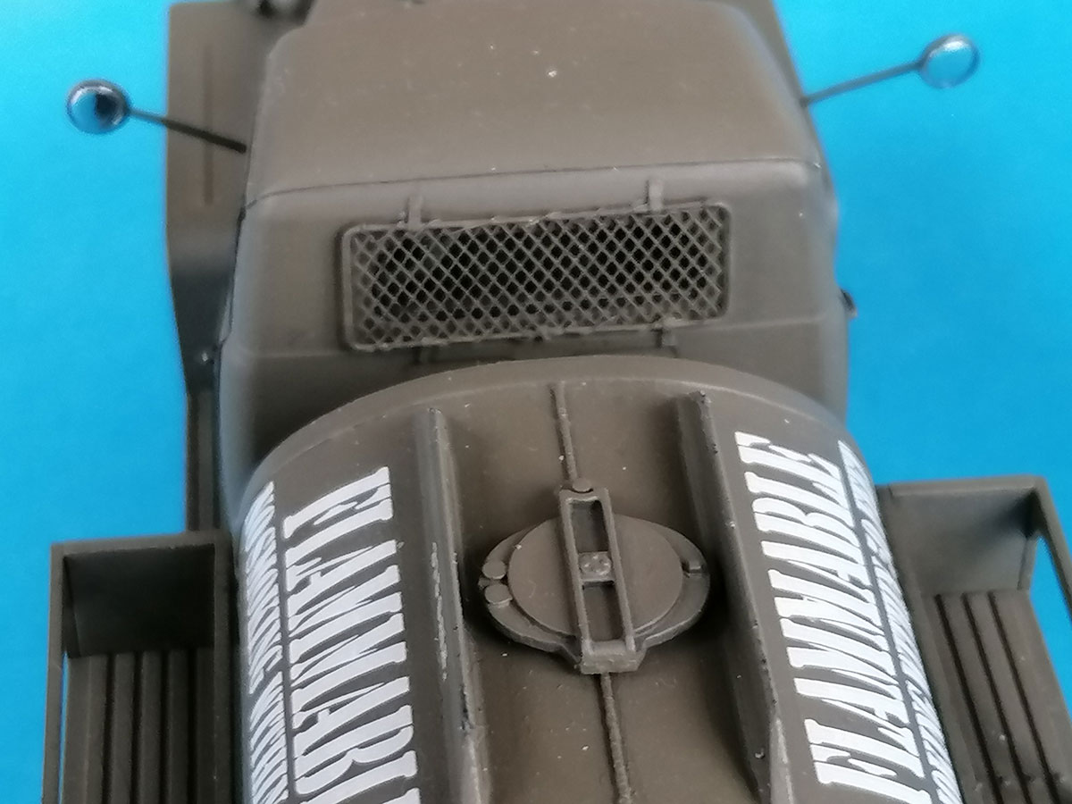
The rear cab window now has seal imitations inside and out and fits perfectly (but still lacks a slight upward bulge at its top – the same oversight as on Italeri's and HB's CCKW). I made the protective net from Aber S07 brass netting in a frame of 0.4mm wire, installed with narrow styrene strips; I know it wouldn't be really helpful in front of the tanks, but it seems that Studebaker delivered all truck chassis with it, no matter what structure they were supposed to carry – just like the internal rearview mirror. (For the same reason, I later added trailer securing chain eyes to the rear bumperettes.)
When joining the roof to the engine side walls, you'll probably get a rather wide gap at the cowling sides. Now before you break out the sanding sticks and putty, look at your references first (for example https://panzerserra.blogspot.com/search?q=Studebaker+US+6+%2B+trailer ), as this seam appears in very different forms: non-existing, very fine, very wide, and even down at the level of the fenders! I have no idea why this was the case, but I just cemented in some stretched sprue to reproduce a recessed wide seam.
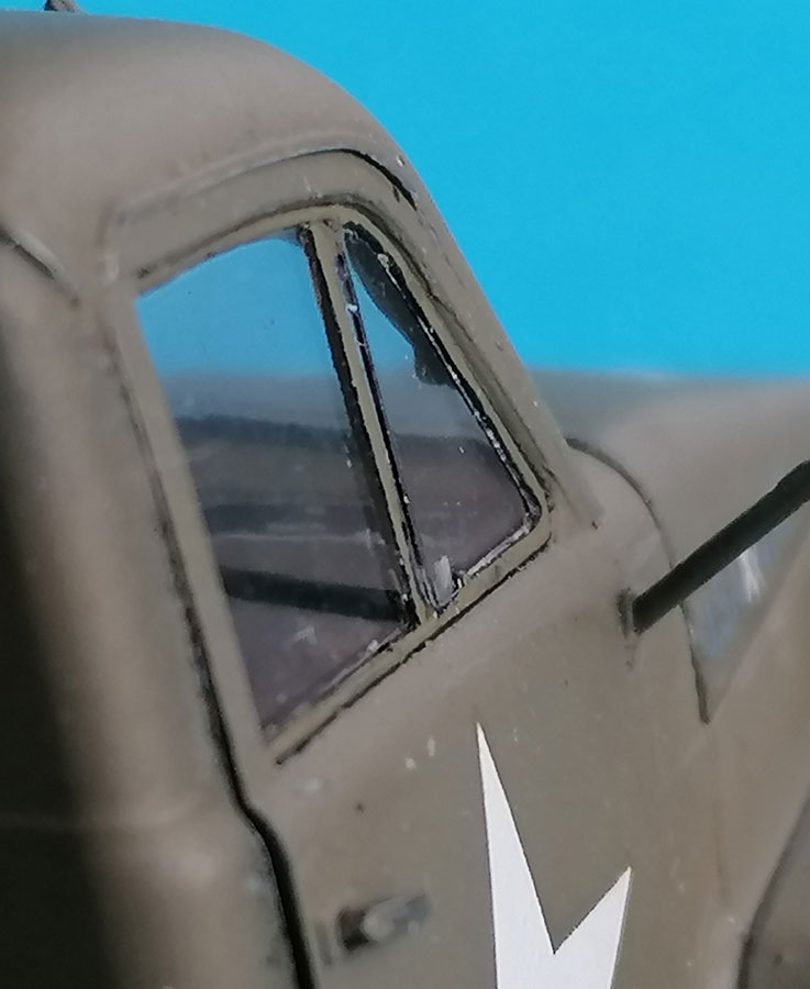 On the prototype, the doors' main window pane has a thin narrow frame that is slightly wider on the inside of its forward facing vertical part, so this can go behind the unframed rear edge of the vent window, providing a seal for that. The way the kit gives this is still wrong: there is a raised "frame" on the outside that separates pane and vent, while there's nothing on the inside representing the pane frame seal. As I didn't want to repeat all the work I had put into my first Studer cab's vents, I just painted a black "seal" on the inside behind that outer ridge; that extends half a millimeter onto the main pane. That part was painted on the outside, too (in OD). This way, the rear edge of the vent remains unframed as on the prototype.
The outside rearview mirrors should be cut off the sprue as early as possible, as they're extremely prone to bending or breaking. They were "framed" with 0.25x0.5mm Evergreen strips to receive reflectors from mirroring foil (cookie pack) that were punched out with a paper punch on a cardboard support, which made them slightly convex. That cavity was filled with a non-shrinking glue to mount the mirror into its frame.
 Another problem comes from the headlights on sprue A: The original sin here is that the lamp bodies seem to incorporate what would be the chrome ring around the glass on civilian lights, while the transparent insets F1 don't go into these rings, but have their own ring molded around the lens representation. Which makes painting difficult and the lights very long, so I thermo-formed an acetate lens that fits into the ring of A10. The reflector is from very thin glossy aluminum foil formed around the rear end of a drill bit.
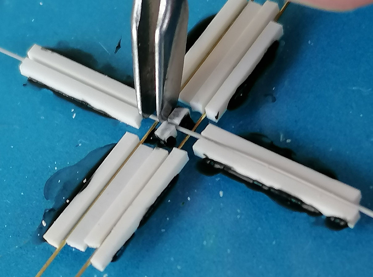
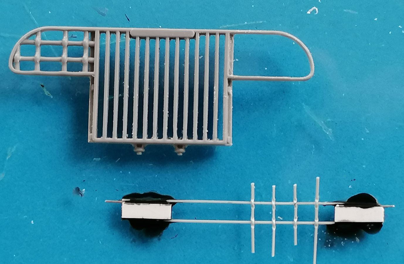 The headlight protecting gratings of the radiator guard were too thick for my taste, so I cut them out and made new ones from stretched sprue. On most US military trucks, the horizontal and vertical rods that formed these things simply crossed on top of each other; Studebaker's, however, had the vertical ones go halfway around the horizontal ones so they were all in one plane. Which forced me to make a jig to bring the necessary "bumps" into the verticals at a constant 2mm distance. Cementing four each of these to horizontal stretched sprue at the different right distances required another sort of jig. Thinning down the frames was easy, installing the gratings into them much less so.
 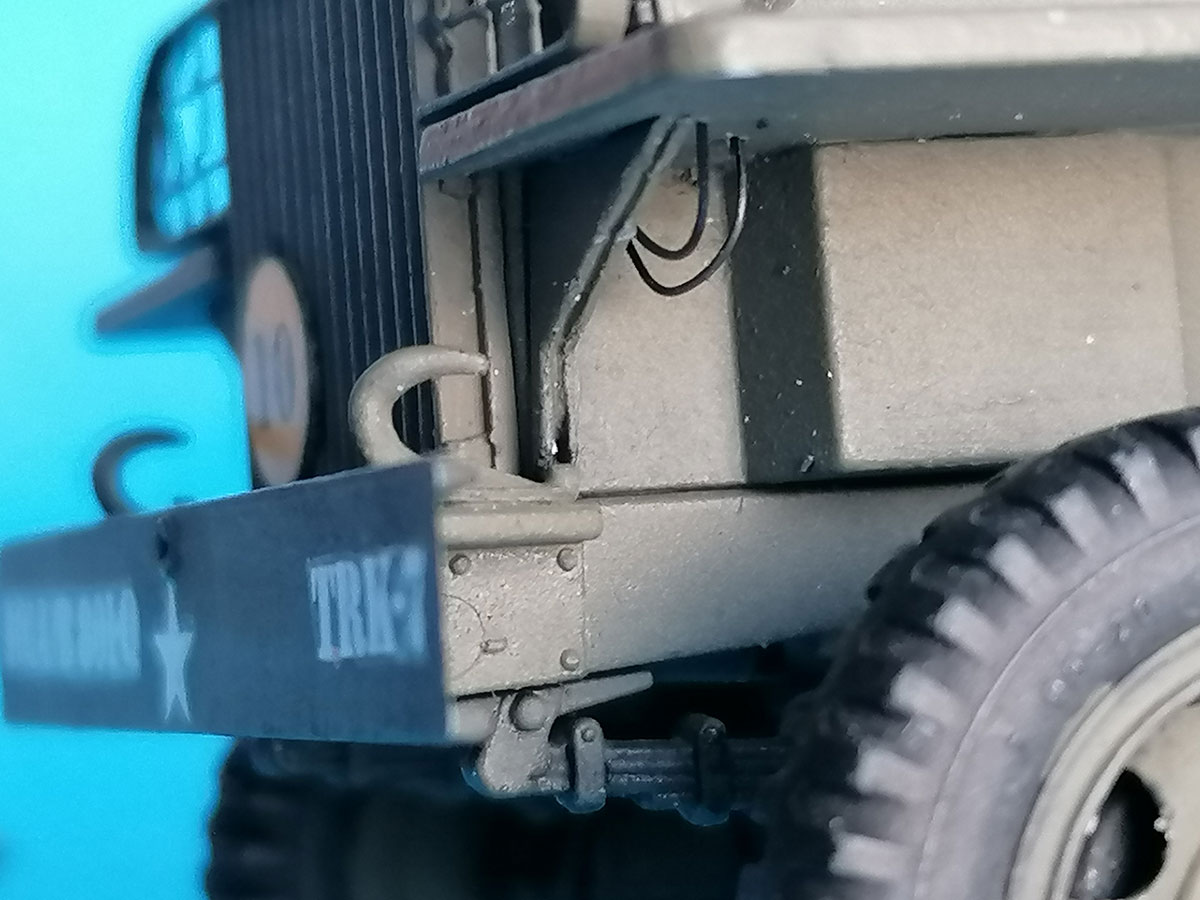 Lacking another "Studebaker" decal from Archer, I removed the name plate from the grille. – Hood clamps from TMD were added next to the grille.
The fender braces 34A had their longer "legs" cut off following the line of the triangle, as the horizontal part can't be seen behind the downward bend of the fenders' sheet metal, which is lost in the kit parts' thickness. And as the braces are made from two pieces of sheet metal, I scratched in a fine line.
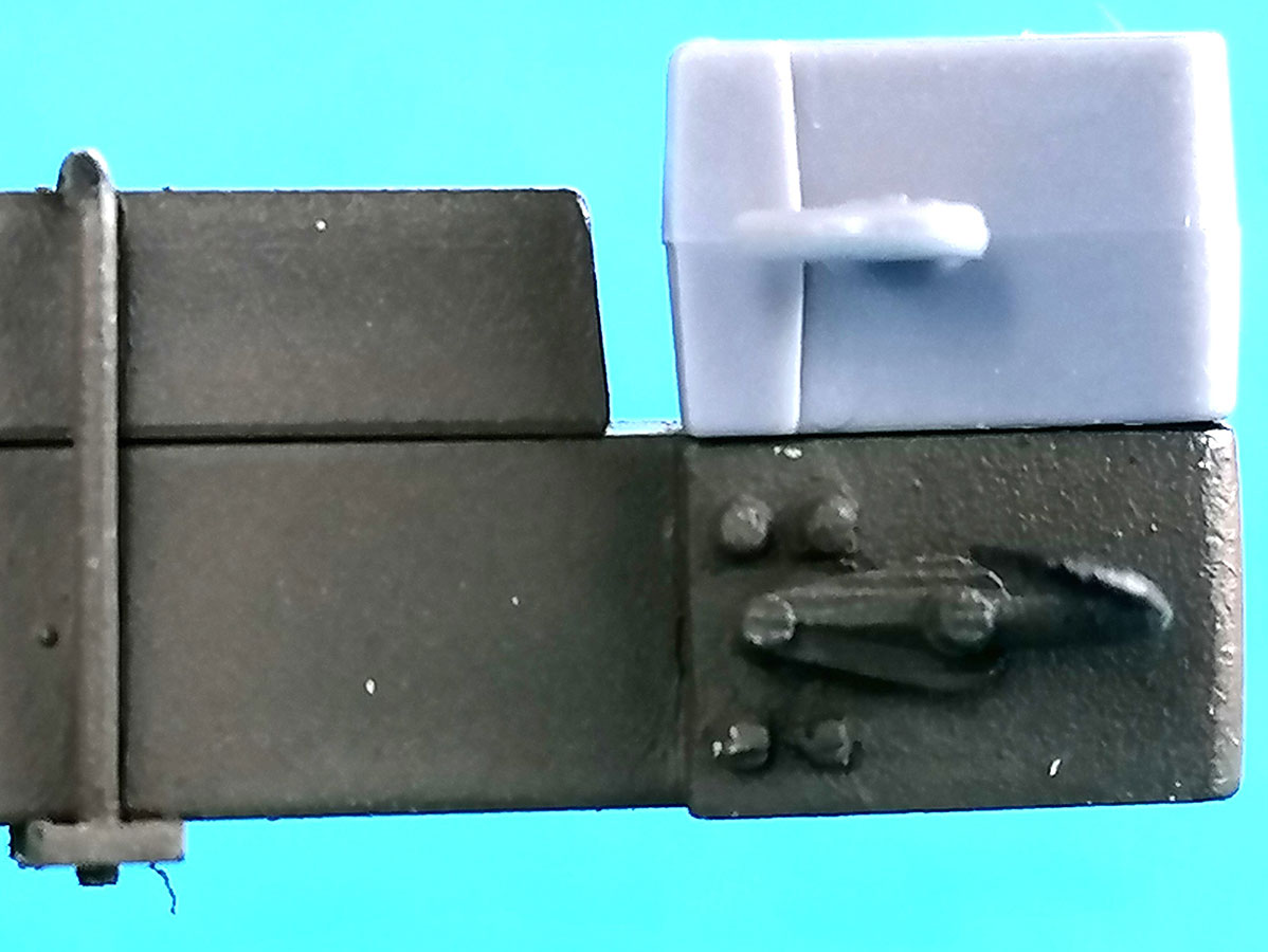
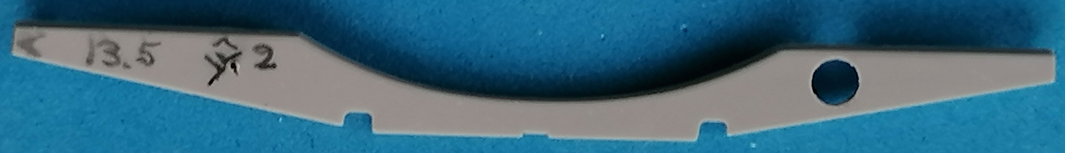
ICM apparently made their kit after pictures of what I think was a development study, shown in Allied-Axis 21, as the vehicle shown there has no taillights, just reflectors on the sides and mudguards. The kit faithfully reproduces that, but I don't believe any so equipped vehicle would have been accepted by the military. As the tank superstucture for both CCKW and Studebaker trucks was delivered by the Heil company, I surmise that the carrying structure was identical and showed what Hobby Boss has made for their CCKW tanker: Holes of 3.5mm diameter were drilled into part D10, with their centers 13.5mm from the sides and 2mm from the top. Correct (i.e. different) taillight resin castoffs were set into plastic strip "C" fixtures behind these holes (which later required cutting down one corner of the rear mudguards).
Note that only the oval on the top left is a red light, while the three slits should be somehow dark. – The reflectors all around the tank rack had punched out pieces of red aluminum foil (chocolate wrap) affixed with Future.
 I chose to show the Reverse Lend Lease vehicle, which meant that (only) on the left fender, a British blackout light had to be installed (B34). But after the trouble I'd gone to making a correct US headlight, I decided that the driver of my model had found and installed that on the right … All lights here were cabled with stretched sprue.
 The tanks received a "weld bead" on top from 0.5mm Evergreen rod, softened with liquid glue and structured with a knife blade. The manhole covers are much closer to the TM illustrations than the circular Hobby Boss ones, but they, too, differ from the TM. The rather clunky mudguard braces were replaced with 0.25 x 1mm plastic strip without the horizontal connection; the mudguards themselves were reluctant to go into the shallow grooves for them that were longer than the guards' glueing edge. – The kit's faucet is (for me) passably correct, so I just added a slice of 0.5mm sheet to represent its locking cap. For what more could be done, see my build report of the other kit. – To discharge static electricity, a chain from the model railroad range was added.
| Painting / Weathering |
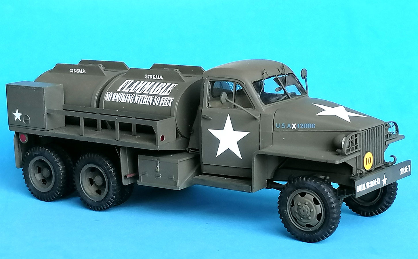
The hate part for me, as always. I used Vallejo Model Air 71.043 US Olive Drab over Citadel Chaos Black.
Markings
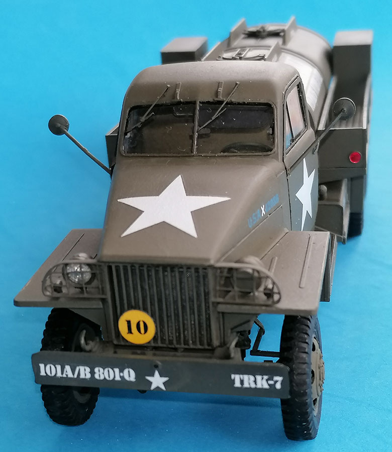
The comprehensive decal sheet is printed with minimal carrier film and the thin decals are commendably strong. Unfortunately, my sheet had a minor misprint: the Reverse Lend Lease indicating white "X" stood lower than the blue rest of the registration, so these decals had to be cut apart and correctly pieced together again. All other markings went on without trouble; for the yellow "10" on the grille, however, I had to cut a 0.25mm styrene plate of 6mm dia to stick it on.
| Conclusion |
A kit that is miles ahead of its Hobby Boss CCKW tanker "competitor". As shown, there are a number of things that could have been better, but I found nothing that couldn't be corrected without too much work. It's just regrettable that ICM didn't incorporate the cab roof corrugation when they corrected the cab floor.
And one more thing: The photo of the presumable prototype shows the end of the exhaust tube horizontally IN FRONT of the mudguard, whereas in all pics of standard Studers it is bent downwards BEHIND the mud guard, mirroring the one on the CCKW 353 – no idea what would be correct here.
Evaluation:
| Price / Value: | ***** | Fitting: | ***** |
| Detailing: | ***** | Skill Level: | ***** |
 |
 |
 |
 |
 |
 |
References:
- Tankograd Technical Manuals Nr. 6037
- Allied-Axis Nr. 21
- https://archive.org/details/TM9-807/page/n2/mode/1up?view=theater
© 01/2026 Peter Schweisthal
845 readers of this report since 01.01.2026