|
|
 |
| The Original |
Elsewhere so much has been written about this Armored Recovery Vehicle that I can limit myself to reminding that the M88 was updated to M88 A1 and then to M88 A2 Hercules. While the external differences between the A1 and the original M88 were only the added APU housing and the relocation of the vise, the A2 has additional armor and many more visible differences. – Helpful photos can be found at primeportal.net and toadmanstankpictures.com .
| The kit |
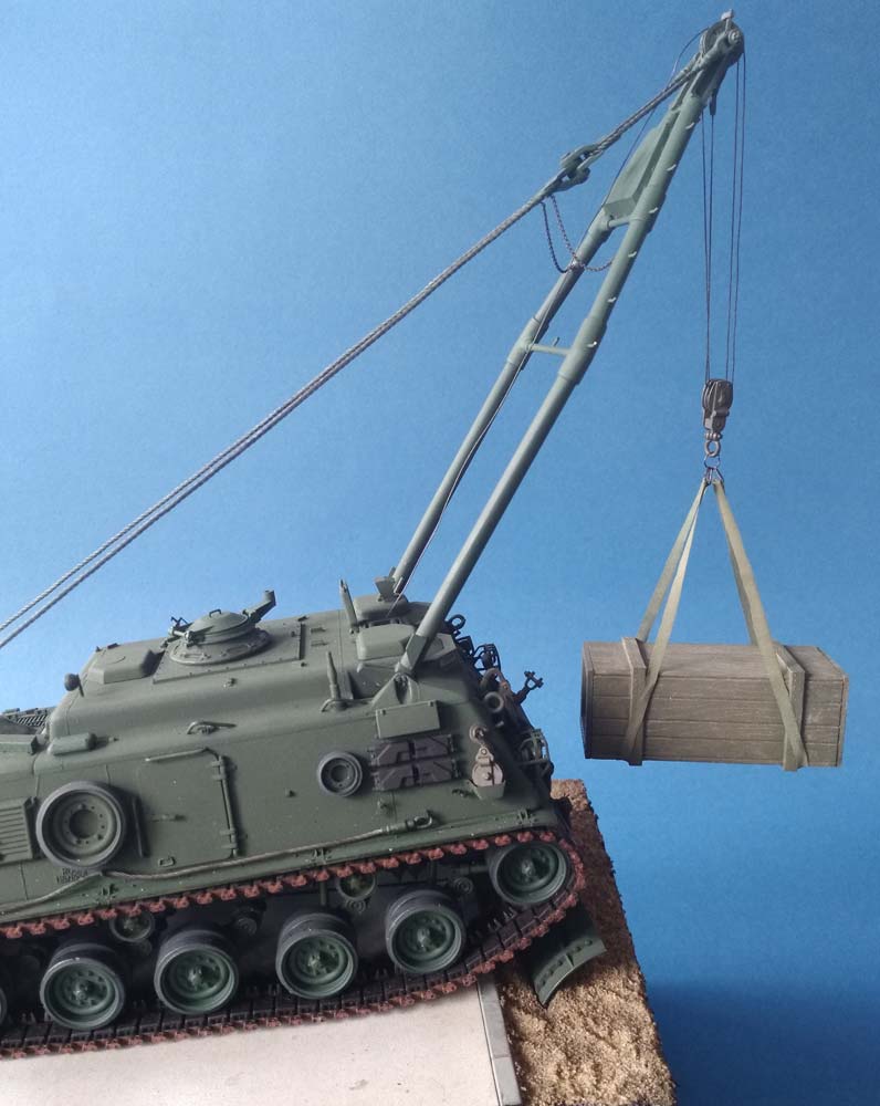
The AFV Club kit is more than 20 years old (the molds were leased out to Revell for some time, too), but still remarkable. There are lots of pictures of finished models in all imaginable situations in the web and in magazines, many with more or less complete interiors, but surprisingly, none with the tank raised on its support spade (the use of this blade as a dozer is expressly forbidden). The reason for this being that AFV Club didn't provide for the model to be shown this way and that correcting means an awful lot of work.
| Der Bau |
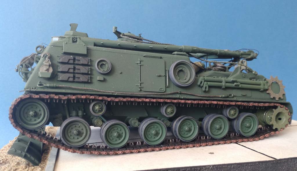
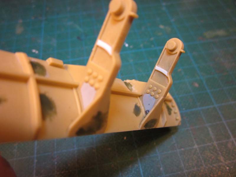
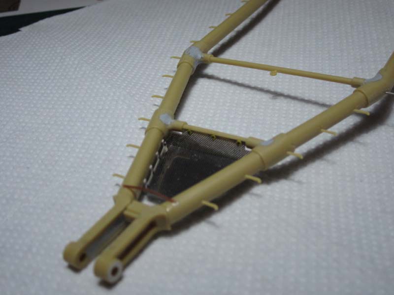
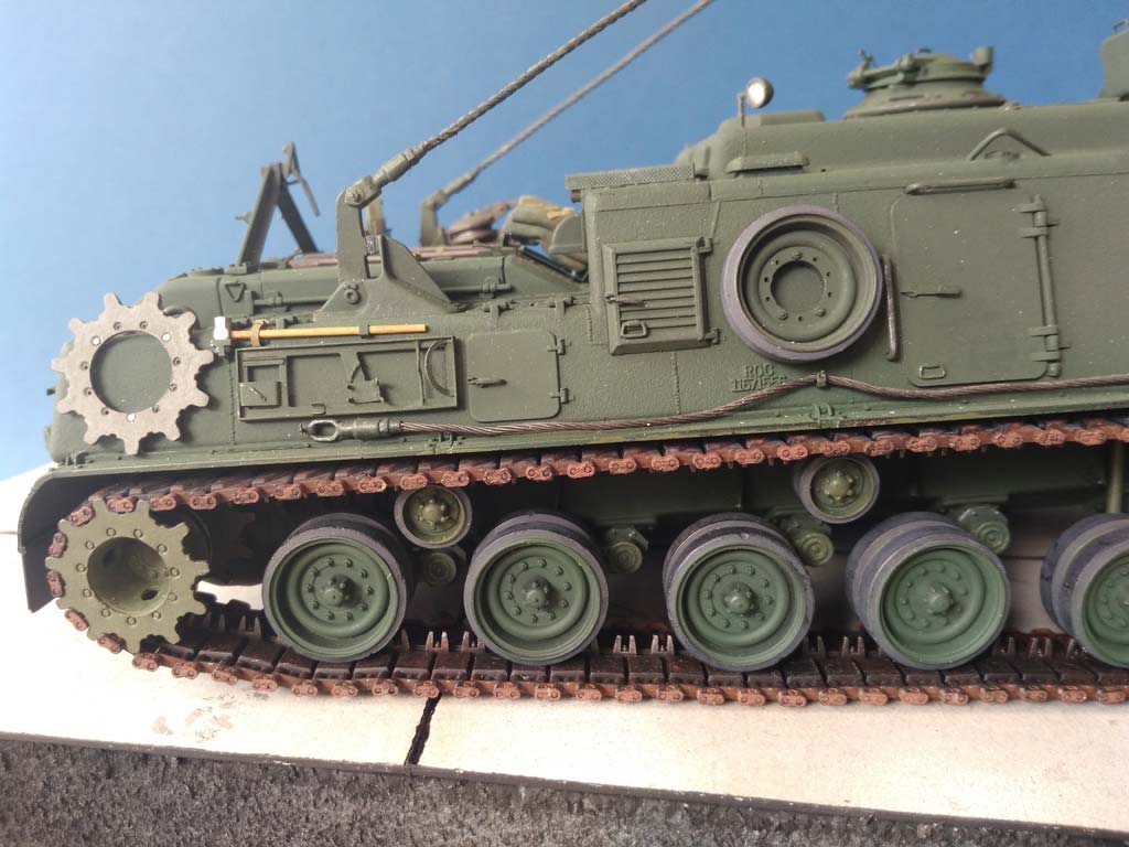
 A quick look underneath a real M88 (or any vehicle with M48 running gear) will reveal that all road wheel arms have one or two "bump stop pins" sticking out towards the hull: these will limit the swing arms' upward movement by hitting the bump stop braces and springs on the hull. The kit arms have appropriate holes, but no pins.
The idler wheel's full name is "Front Compensating Idler", because it is moved forward and back by its linkage to the first road wheel arm, thus compensating the track slack that will result from that road wheel being pushed upwards. Now that wheel couldn't fulfil this job if its axle went through to the hull, as on the kit parts C 5/6; instead, its "swing arm" is mounted eccentrically to the hull, and the linkage to the road wheel arm is movable.
The shock absorbers, of course, also vary in length depending on their respective swing arm's position.
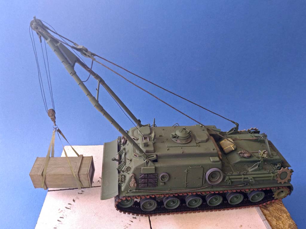
Studying all available photos, I found that, on even ground, swing arm #4 hardly moves out of its parking position when the ARV is raised on its spade. Other modelers had reported that the spade's braces were too long, and I found that to be true.
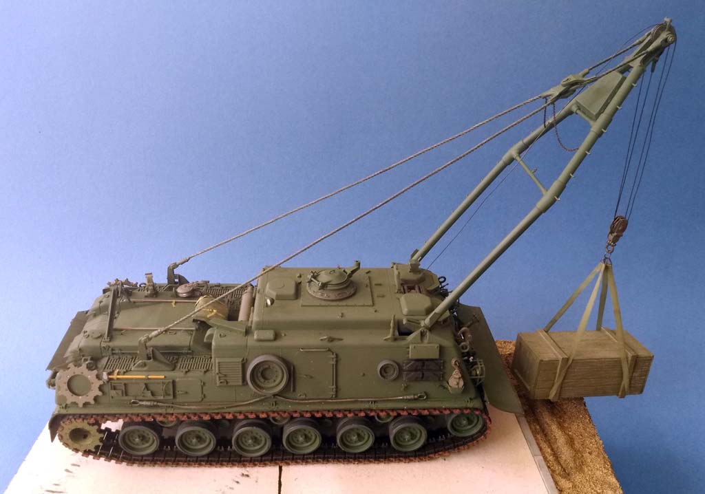
A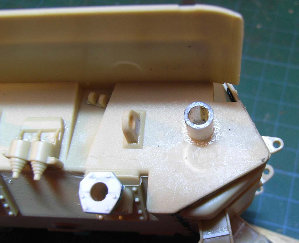 bove all, here's a piece of advice that will save you a lot of trouble no matter what you do with the running gear (and trust me, this comes from experience). The kit's instructions tell you to complete the A-frame rather soon and to mount it to the hull. Which in a way is justified, as you won't be able to thread the boom's hydraulic rods into their cylinders once you only have the hatches left to work through. On the other hand, this immensely raises the risk of damaging the boom's steps and other details. The solution is to leave the boom proper off its hinged hydraulics (B 3,4,5) while you paint and mount these and only glue the boom to its feet when that can be done with impunity.
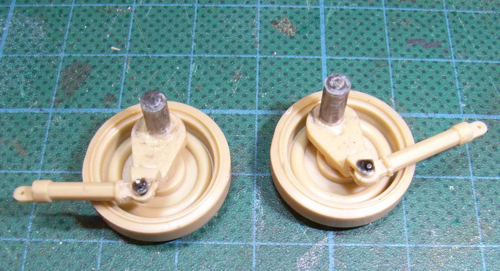
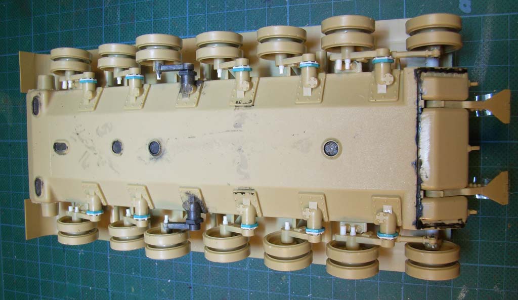
For the running gear in the "up" position, the "keyed" ends of the "torsion bars" were "unkeyed" by cementing on thick styrene sheet and filing it into a circular diameter, except for the #4 position. With a drill bit of the right size, the tubular "road wheel arm supports" on the hull also had to be freed from their "keys", again except #4. As the torsion bars are staggered, with those on the left lying in front of their right hand side counterparts, the spade raises the hull around the axle of the #4 wheel on the right, with swing arm #4 on the left slightly going down at the same time. More about the way out of this later.
As a real nit picker, I noted that the kit's octagonal "road wheel arm retainers" are molded to their road wheel arms and would rotate with them. Which would hardly be noticeable on a dirtied running gear, but I cut them off and replaced them from 0.5 mm sheet, plus a 0.9 mm "mounting ring" on the tubes. Slices of styrene rod were cemented on as bolts, and thin sheet strips as spacers to allow the arms to move over those bolts. If I could cast parts, I would've done it here. – The "bump stop pins" on the swing arms were added from two sizes of styrene rod: 2 mm as "secondary" pins where applicable and the same rod drilled out everywhere else to receive 1.5 mm rod to form "stepped pins".
Now the spade had to be inspected. It was assembled with white glue and tape, then the swing arms #4,5, and 6 were dry fitted and everything was raised on the spade. As mentioned above, road wheels #4 should always stay on the ground, but both had liftoff, even with a piece of track beneath them. Seems the spade braces really are too long, some 1.5 to 2 mm. Basically, it shouldn't be a problem to shorten them, BUT: Their hinges inside the hull are placed in such a way that the too-long braces bring the spade into a correct position when it is stowed. Which means that shortening the braces would also require repositioning the hinges upwards to keep the possibility of a correct stowed position.
Maybe someone with better math abilities than mine could figure out that one, but I was already sufficiently exhausted from work on the running gear to be in no mood to face that test fitting orgy lingering there. So I decided that the model would be placed on somewhat uneven ground where the spade could be positioned lower than road wheels #4 and contented myself with filling sink holes and adding a strengthening rib on the braces. – With this problem out of the way, I returned to the running gear.
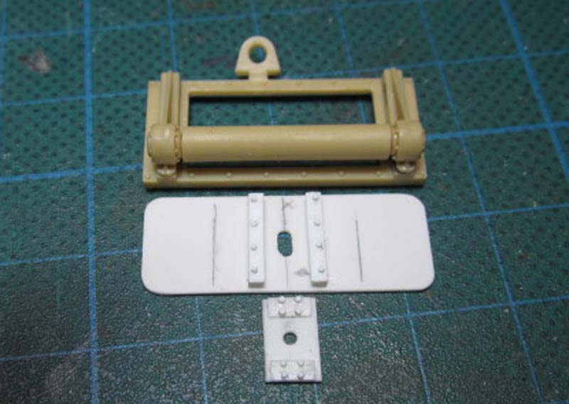
 For a correct mounting of the idler supports C 5/6, first I drilled through the joint and then cut out the link to the first road wheel. Next, I eyballed the center of the plate above the axle and drilled through it with a small drill bit. The part was then dry fit so this hole was vertically above the kit's axle, and that point was marked on the hull. The hull wall was then drilled right through with increased size drill bits until a new styrene tube of the right diameter could be fit in. As it turned out, the finished hole very slightly cut into the kit's locating tube, which was now shaved off. The replacement tube was cemented into the hole and onto a piece of 1 mm sheet that was cemented to the hull's inside for additional strength. The wrong mounting axle was also cut off and a new, slightly longer one (to go through the hull wall) cemented over the small hole in C 5/6.
 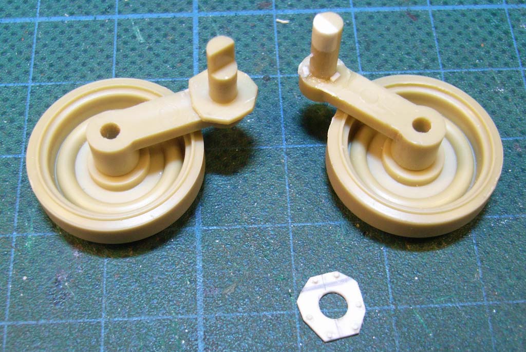 This mounts the idler support eccentrically so the wheel can move as needed.
The linkage was joined movably to the idler support and to road wheel arm #1 with stretched sprue pins. If, by the way, you wonder what that black stuff in the photos is: I use thinned white glue for temporary attachments, and to be able to later remove that without overlooking transparent residue, I keep a little bottle handy in which I have some thinned white glue colored with black gouache.
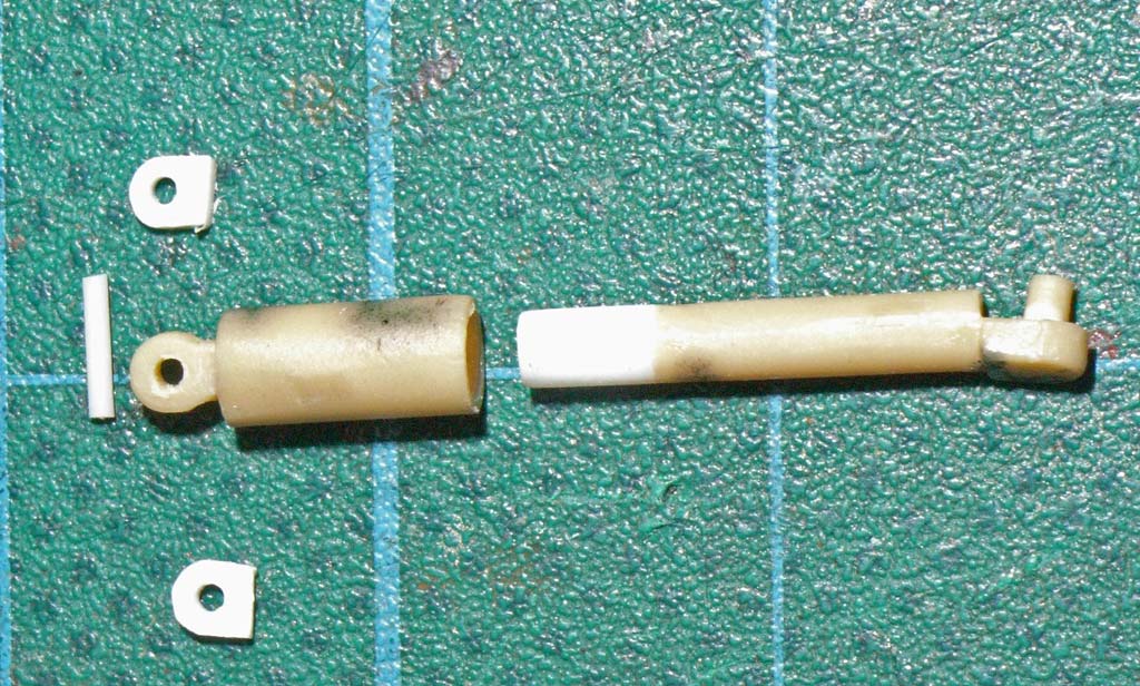 As mentioned, the shock absorbers have to be shorter or longer according to the swing arms' positions. Instead of much measuring and calculating, I cut them all apart and drilled out their upper parts while adding pieces of Evergreen rod to the lower parts. With the pair that were to go to the #1 position, I made sure that they could be “compressed“ only so far as to support the vehicle in an exactly horizontal position when not raised on the spade. Perforated new upper mounting brackets on the hull were made from sheet styrene. To affix the lower ends to the swing arms, I think their mounting tabs should be bent inwards no matter what else one did with the running gear; mounting was done by cementing small plastic discs to the pins protruding through the mounting eyes on the swing arms. For the expected movement of the shocks, I drilled through their upper mounting points to install stretched sprue pins.
 To mount all this, I started with swing arms #1 (plus shocks) and #4 . Of the latter ones, only the one on the right was cemented in when the model had been balanced out into a totally horizontal position. When the cement had cured, the model was raised on its spade (with tracks mounted, and compensating for the too-long braces!). The little play that the poly caps allow and some slight whittling on the swing arm key were sufficient to place the left #4 arm at the correct angle (found after much dry fitting) and cement it there. All other running gear could then be mounted without cement. To keep the model from shedding the AFV Club single link tracks AF3505 that I substituted, I cemented all support rollers in and tied all road wheels to the track links below them using fine wire.
 I rebuilt the recovery winch outlet movably and widened the hole behind it into a slot so the rope can come out at different positions. The upper hull offered no problems except for the commander's cupola. This is not well detailed and sits too close to the hull roof. The ideal transparent replacement part would have come from AFV Club's M40 kit, but as I didn't have that, a "standard" Sherman cupola had its periscope openings drilled out and filled with clear styrene from a candy box. The hatch received a hold-open hook.
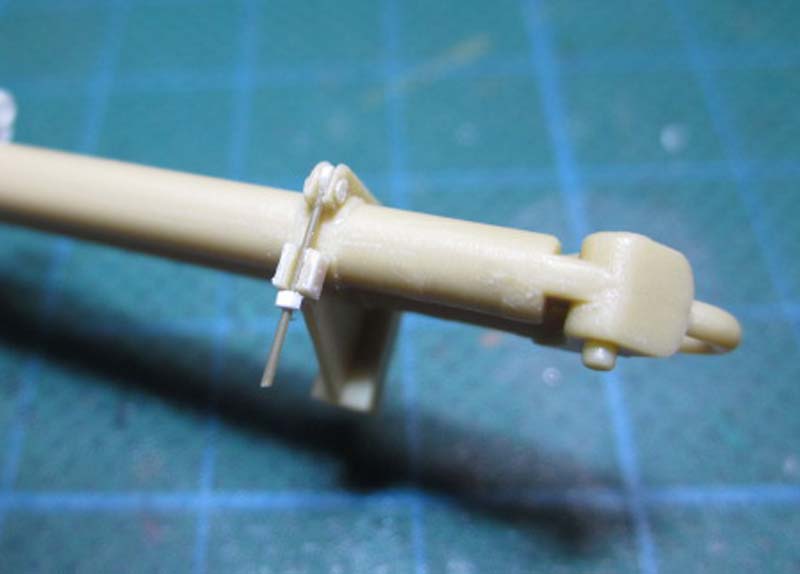
 For the hoist winch, I took considerably thinner thread than the kit-supplied one. Into its roof opening, I cemented two 2mm rolls (like the things AFV presents in the "Vietnam version" kit) plus a suggestion of a cable guide tunnel below them. – I had the very old Eduard PE set 35098 and used some rope clamps and the exhaust deflector from it; apart from that, only stowage box handles from TMD were used. On the draw bars, the stowage casings for the shackle bolts were replaced together with the bolts themselves and their cotter pins (the latter bent from 0.3mm brass wire). The bar at the rear had its kit stowage clamps thinned with a saw and then "bolted" in place with stretched sprue. A few engravings brought out that the bar hinges consist of several parts.
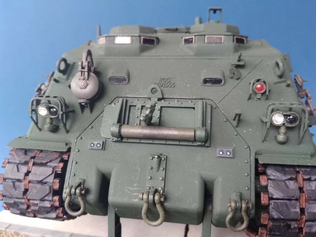
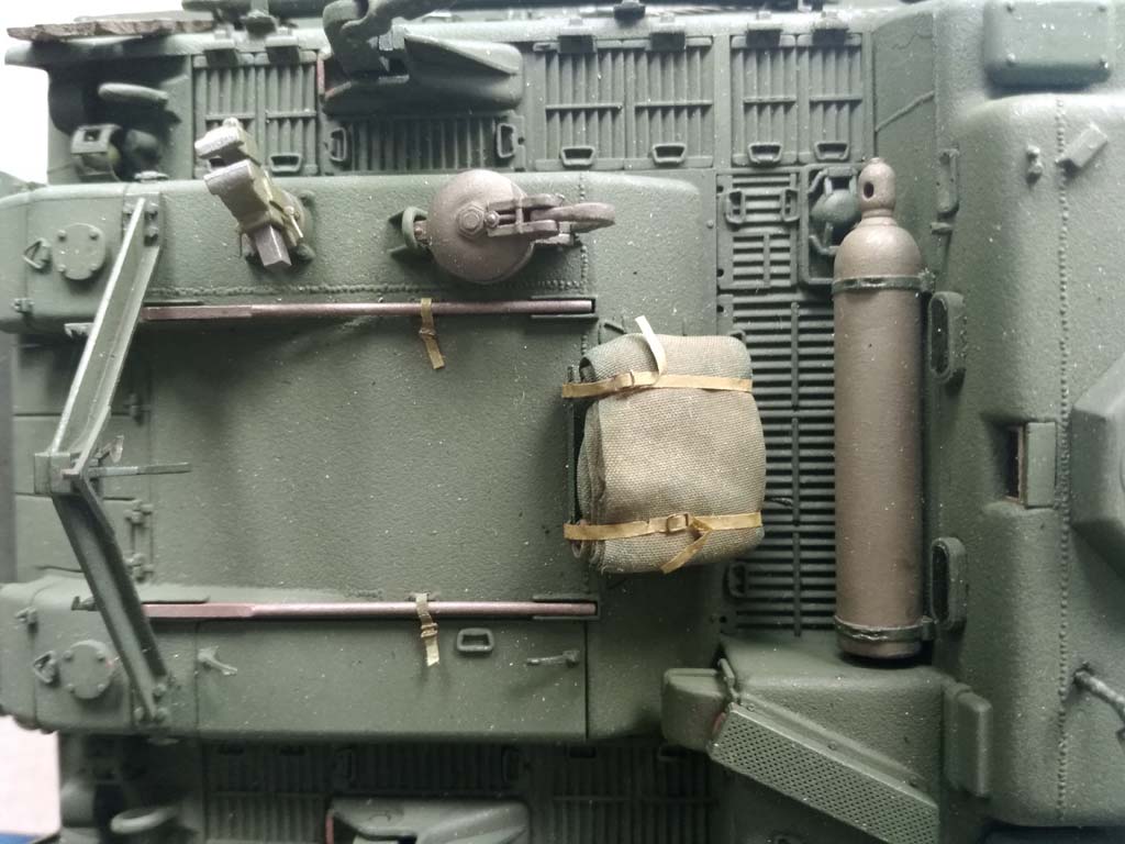
 Next to the rear vision blocks, there's another little part that looks like them (A14) and, according to the instructions, should be mounted angled downward. In all prototype photos that I could dig up, this thing's "view" is upwards, plus it's w/o glass and painted over – maybe because it would be a peephole from the acetylene bottle locker? Anyway, the connection to this bottle has to be added next to this part. The armored cover of the rigger's periscope A11, on the other hand, has to be shortened so it'll end above the glass front. Speaking of glass: I covered all glass outlooks with slices of acetate that were painted black on the inside.
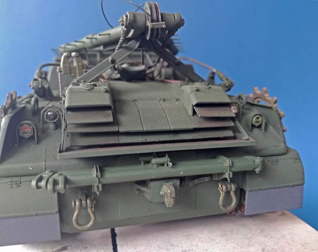
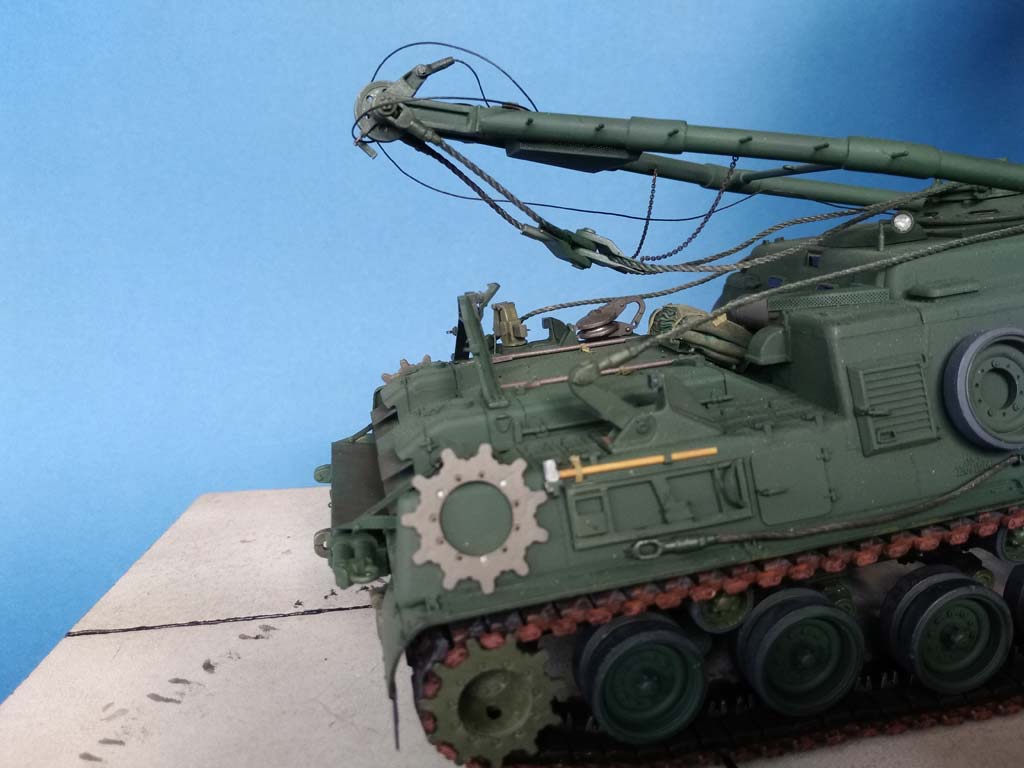
On the engine deck, a few little things could be corrected: For example, the vise's handle is depicted in a vertical position, but unrealistically only halfway down. I cut it off and let the replacement "fall" down all the way. The A-frame's support received bolt heads on its bases and more realistic hold open hooks for exhaust grills in the folded up position. The arrester hook at the top of the support was mounted movably, and to enable it to hold the A-frame down, its counterpart on the frame had to be thinned. Parts of the prototype's exhaust armor can be folded to the sides after loosening the arresting bolts. But that demands hinges to be added, and the triangular lifting eyes on top look a lot better when replaced by brass wire ones.
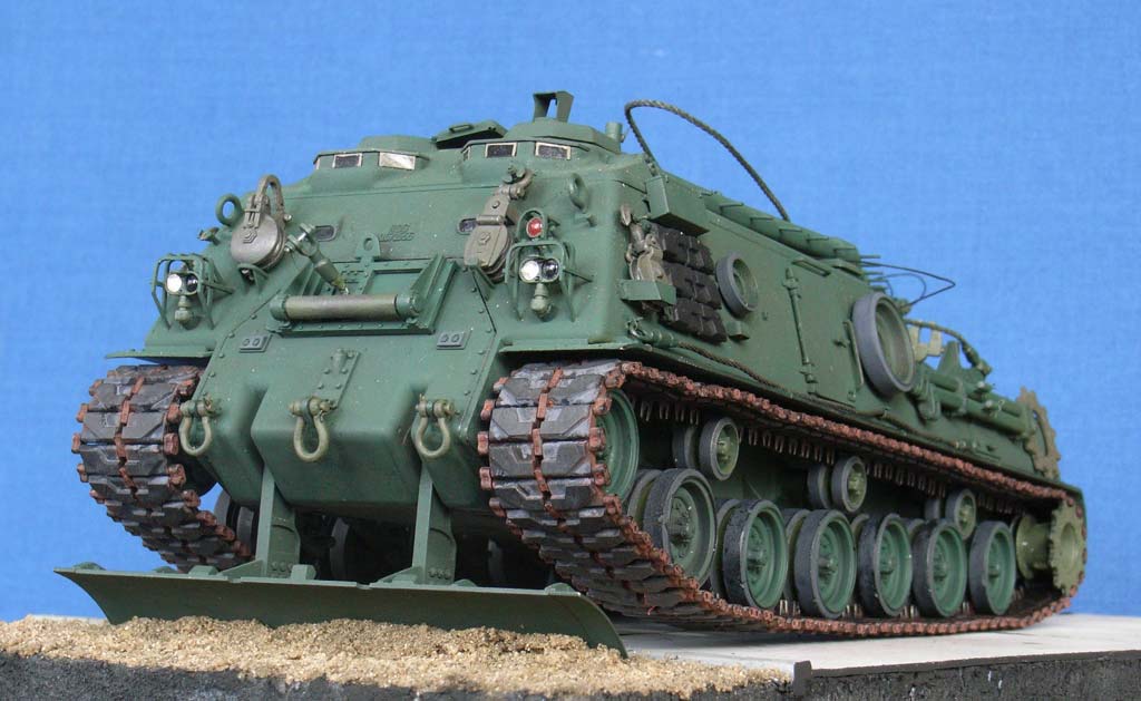
 I drilled out all lights and filled the reflectors with aluminum foil before inserting acetate lenses; the same for the warning light with the acetate's inside painted red with a felt-tipped pen and with blackened lenses (w/o reflectors) for the blackout lights. The kit's light guards can hardly be cut off the sprue without damaging them, and the large ones were also missing a third brace on top (just like the ones from my old Eduard set …). I used them anyway, after thinning them as far as possible.
 The two pry bars were replaced with ones from Evergreen rod that were tied down to stretched sprue footman loops with straps from onionskin paper and Eduard buckles, the tool carrier was detailed and left empty to better show this. The sledge hammer was tied down into Eduard brackets. The handles of the different compartments were replaced with TMD ones.
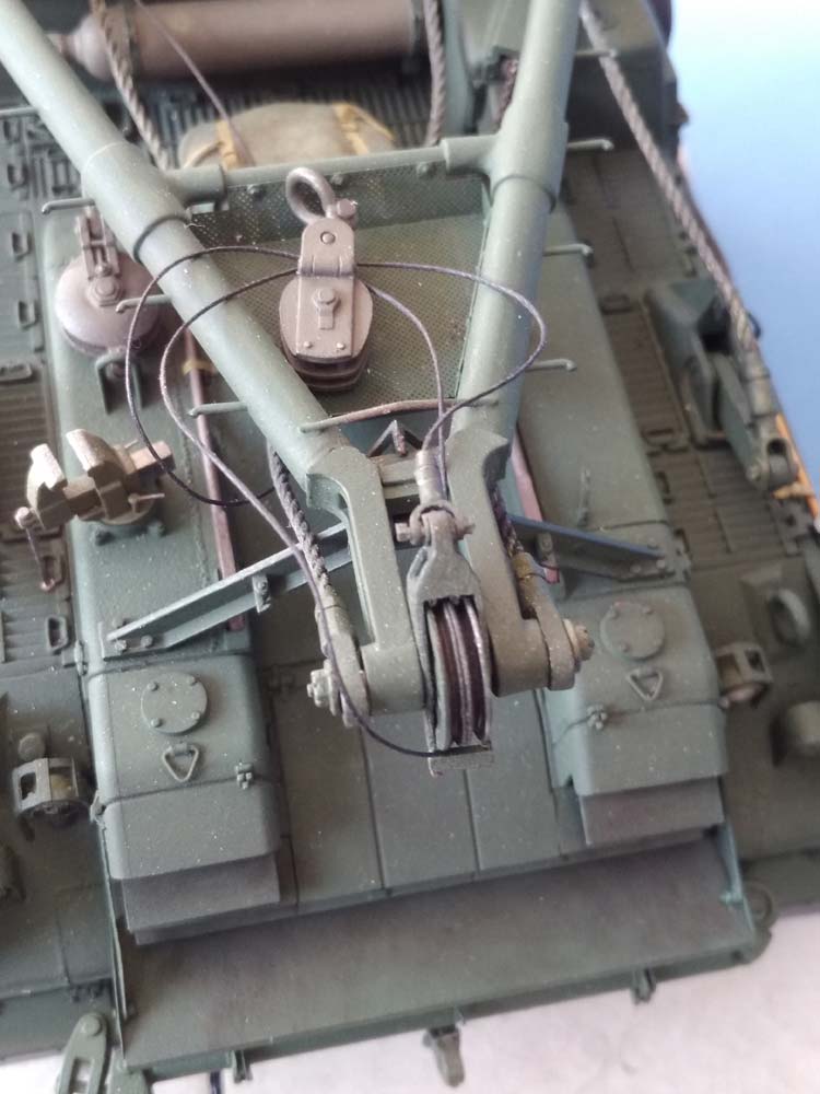
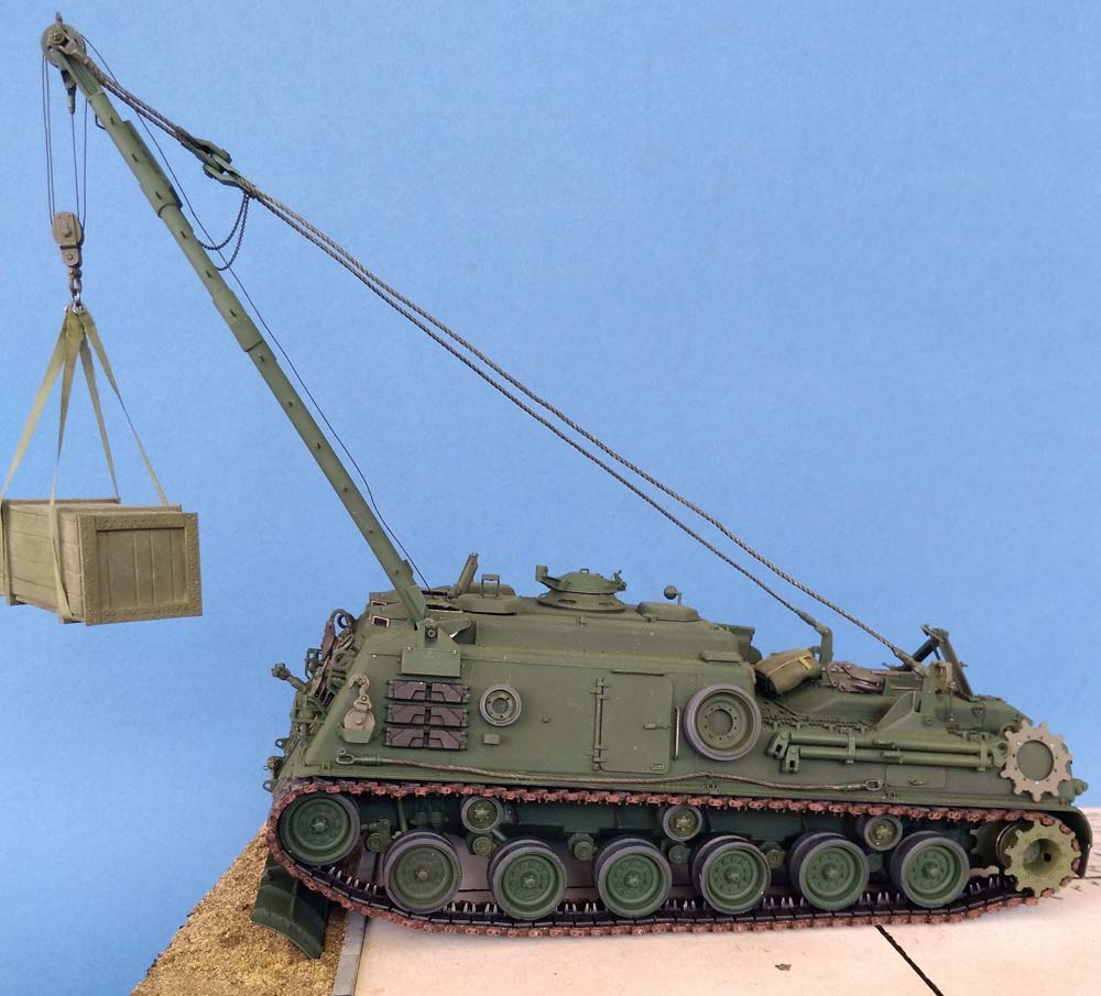
The A-frame received a bent thin protecting rod near its sheave. To mount the PE stowage basket for the block, I sanded off the protrusions on the frame and cemented strips of thin styrene sheet to the longer basket insides. Some cement and softened styrene were pressed through to the outside of the basket and offered a cementing surface that could be joined to new fixing points on the frame. The rear of the basket received three "washers" mounted the same way. All "bolts" were represented by dots of white glue.
 The "X" connecting the two parts of the stay ropes had its upper eyelet cut off and received a small plastic disc for the other end of the bolt that joins its two halves. Two 22mm long fine chains to the side rails hold the "X" during movement of the frame, and the rope anchors on the hull received more distinct "rubber stops". Meanwhile I am of opinion that the shorter piece of stay rope should be about 10mm shorter and the other one 10mm longer than the instructions demand, to bring the "X" into a more correct position on the engine deck. – I detailed all blocks and pulleys to make the hooks and eyes rotatable and their axle pins detachable; the sheave cover at the frame's top is now operating, too. The stowage point on the left of the glacis was detailed to be working, the arresting plate hangs on a piece of latex thread. All around the model, I installed larger brass towing eyes from RB Models; the cotter pins were bent from 0.3mm brass wire, just like those on the draw bars.
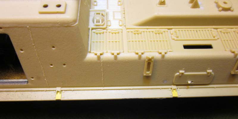
After I had cemented the hull halves together, the seam in the rounded rear area needed some severe sanding, and the "weld seams" to the left and right of the exhaust outlet had to be continued downwards with stretched sprue; the same material also served to line the seams of the lateral "wings". When everything seemed to be ultimately glued up, it turned out that the lateral "running board holders" had no contact to those boards; thin styrene strips solved that problem. The towing hitch was rendered operable (be prepared), and the kit's warped exhaust deflector was replaced by the Eduard brass one. Its lateral braces hook into corresponding pins on the exhaust shroud sides. Eduard also provided the stowage points for the tow ropes from annealed push bike gearshift cable and for the boom stay ropes beside the commander's cupola. The three roof guides for the lifting cable were sanded out of thicker styrene sheet.
| Painting/weathering |
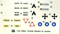
Remain painting. And that is what I plain hate about model building, so: Games Workshop "Chaos Black" from the rattle can as primer. "Forest Green" on top of that was thankfully applied by a modeling friend who had concocted his own Tamiya mix. My models don't get washes and other finesses, only the rubber liners on the wheels were painted dark gray. The "frames" on the acetate periscopes I managed to paint myself. The boom stay ropes were replaced with thicker ones from neon-yellow nylon and were first dyed black with gouache and then treated with gunmetal paint to approximate their color to that of the tow ropes. With the tail lights, care should be taken that only the upper oval on the left one is red, while the other three slits would be dark – well, what? Dark green, black, dark gray, anything but red. Some detachable parts on the vehicle I've painted olive drab, to show that they weren't on board during the last overhaul … Markings will be added once I've decided which unit will be rewarded this vehicle.
| Conclusion |
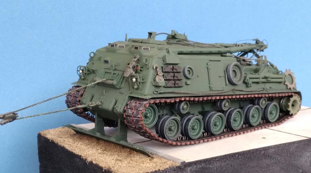
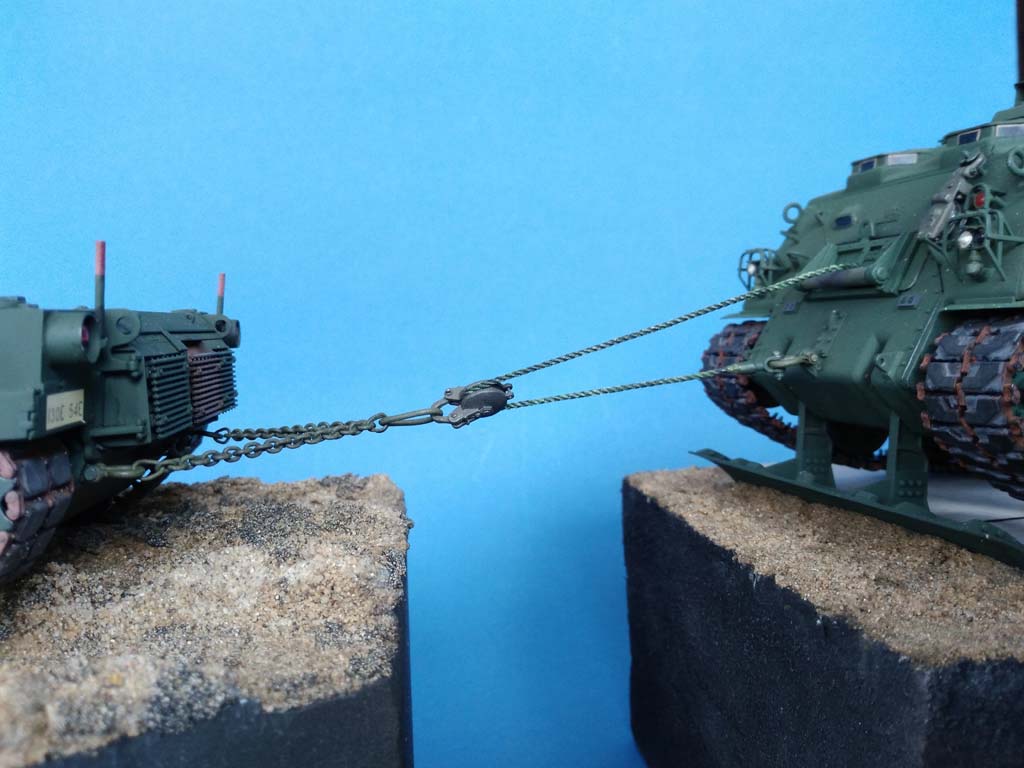
My M88 A1 can now be shown on the march/parked as well as pulling/lifting with and without use of its spade. Anyone wanting to only show their model in the raised mode could certainly save a lot of work on the running gear, but should remember that the connection from idler wheel to first road wheel has to be corrected even if the idler is mounted as the kit's instructions say.
And never forget: It's just a hobby!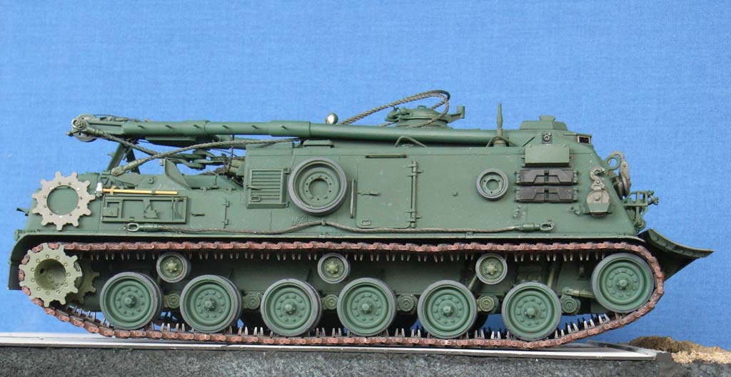
| Price / value: | ***** | Fitting: | ***** |
| Details: | ***** | Difficulty level: | ***** |
 |
 |
 |
 |
 |
 |
 |
 |
 |
 |
 |
 |
 |
References:
© 08/2017 Peter Schweisthal
14311 readers of this report since 17.08.2017