|
|
 |
| The Original |
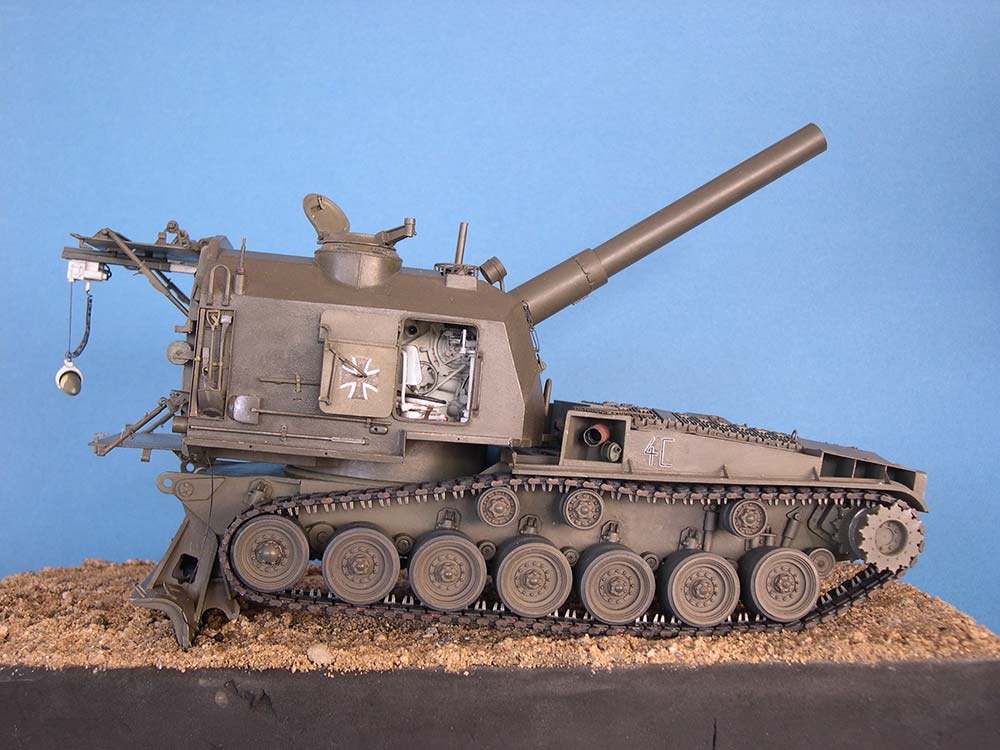
After WW II, the US Army felt a need for self-propelled artillery with fully enclosed fighting compartments. By reversing current tank hulls, the turret could be placed behind the engine. References contradict as to the type of chassis used for the vehicle described here -- some say M48, others M47. As the hull has vertical side walls and the TM calls for T80 E6 or T84 E1 tracks, I am sure it was the M47 that was used for the conversion. On it, two "Full Tracked Self-Propelled" artillery pieces were developed: "155mm Gun Cannon T97" and "8 inch Howitzer Cannon T108", standardized as M53 and M55, respectively, around 1954. Externally, they differed in the size of the gun tubes and the shape of their travel braces: straight for the long gun tube, with a double bend backwards for the howitzer. Inside the turret, ammunition stowage in the right rear corner was 10 projectiles of 203 mm caliber pointing forward or 20 of the 155 mm variety pointing across; capacity of the "powder container" racks on the left differed correspondingly. A projectile hoist was installed in the howitzer only. Apparently, the US Army didn't use these weapons very long, whereas the USMC kept and used both models right into the Vietnam War. Of foreign users, I know Belgium, Italy, Turkey and West Germany; they had M55s, which the Germans kept until 1966.
It seems that the rather limited use of these guns is responsible for the few references available -- there's a photo or two of Marine guns in most every book on the Vietnam War and a short mention here and there, but mainly, modelers must make do with TM 9-2350-210-12 of july 1959; TM 9-3025 of september 1957 is helpful, too, as are some places on the web listed at the end of the article.
| The kit |
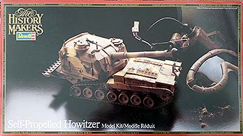
This is the Revell re-release of the old RENWAL kit from about 1960, in my case the 1982 "History Makers" version. Now all RENWAL military kits weren't up to what was state of the art even way back then, but the M55 was the worst of the lot. It claimed to be 1/32 scale, but is closer to 1/30. Mentioning all of its other faults would require several pages -- instead, here are the parts that I used without changes: all "rubber tired" wheels and their suspension (more on this in a minute), the recoil spade blade, and the breech opening lever. Period. Everything else had to be severely reworked, replaced, or added, so this wasn't really a kit but rather an idea for a scratchbuilding project. So, if you want an M55 with interior in your collection, take the Elite resin kit and start scratchbuilding from there -- it won't be more work, I promise! --- And here's something for the small-scalers: the ROCO M53 / M55 model is an exact copy -- of the unchanged RENWAL item, not of the prototype!
| Build |
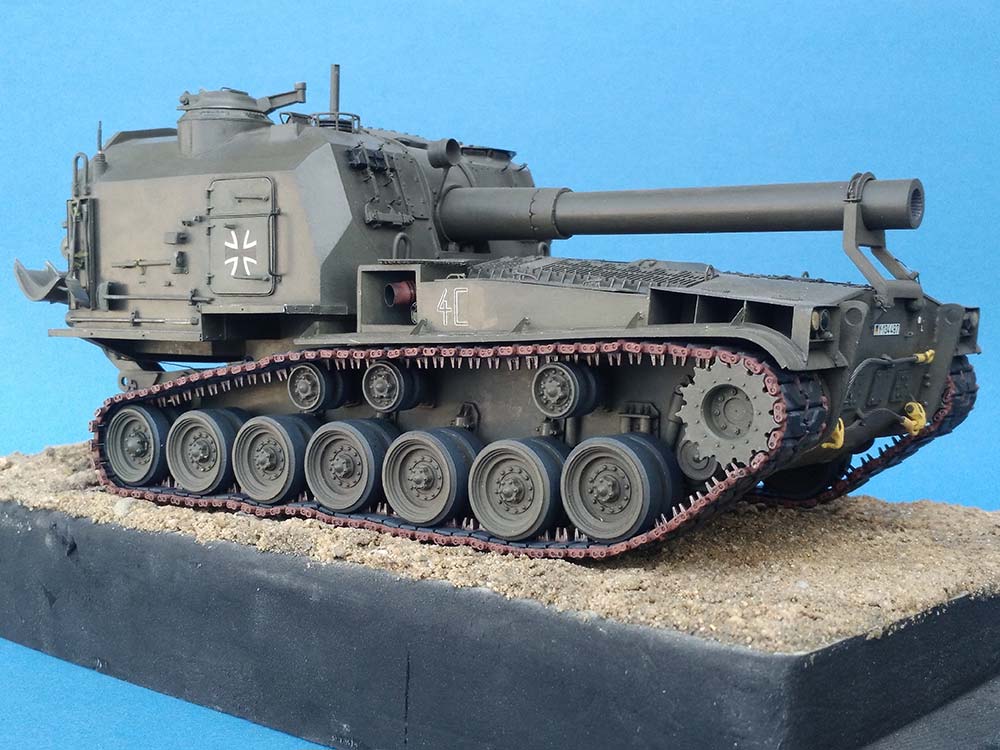
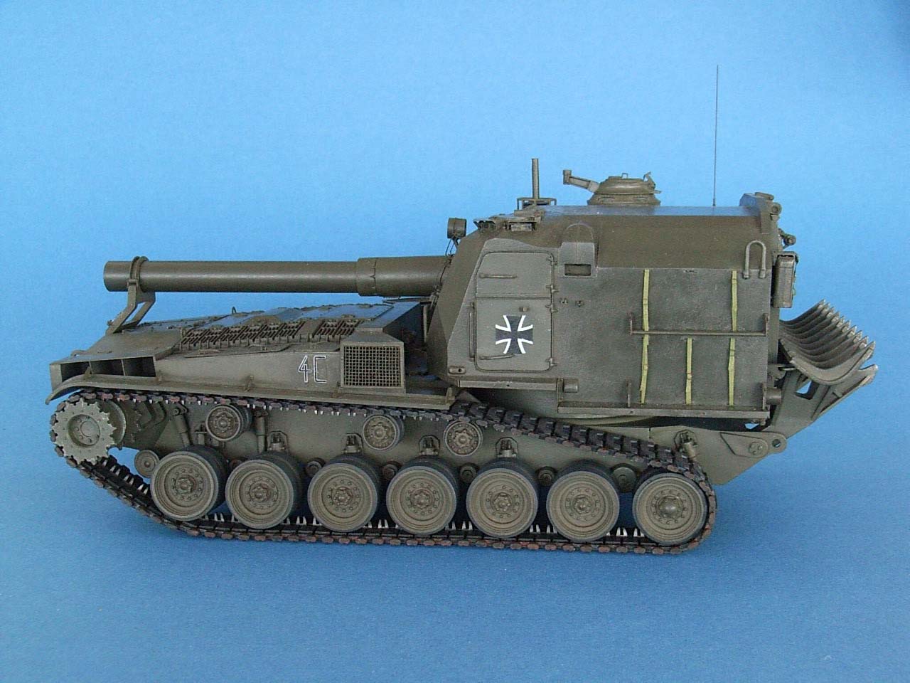
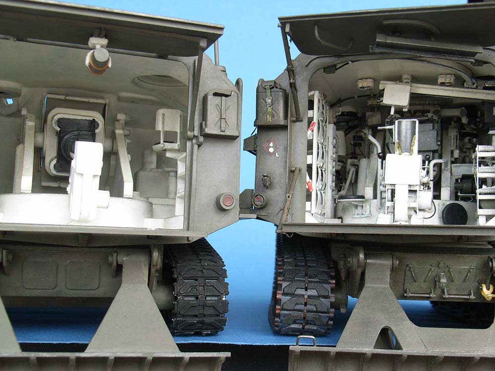
I obtained a Xerox copy of the TM via the Royal Army Museum in Brussels, Belgium, and the friendly folks there also allowed me a few hours inside their M55 (at the time not yet restored, today in the Gunfire Museum at Brasschaat near Antwerp) to take measurements. In hindsight, this proved a fatal mistake, as I'm a super detailer to begin with (OK, OK, so it’s severe AMS), and with all the things I had to build myself, I tried every trick in my book (and got carried away more than once) over a period of 22 (!) years, turning the worst kit I ever worked on into the most detailed model in my collection. I must, however, point out that it took so long not least because after some months of minimal visible progress I always had to build a decent kit, to protect what little mental health was left. I lost count of the actual building time, but estimate it at 1000 hours minimum, plus twice that amount brooding over my references, trying to figure out those decisive details that hid just outside the available illustrations. When the size of the project dawned on me, I also bought another kit and built it out of the box over one weekend to help me rediscover all the changes I was about to make. As describing everything I did would also be unreadable, I'll just list what I think are the most important points.
Hull
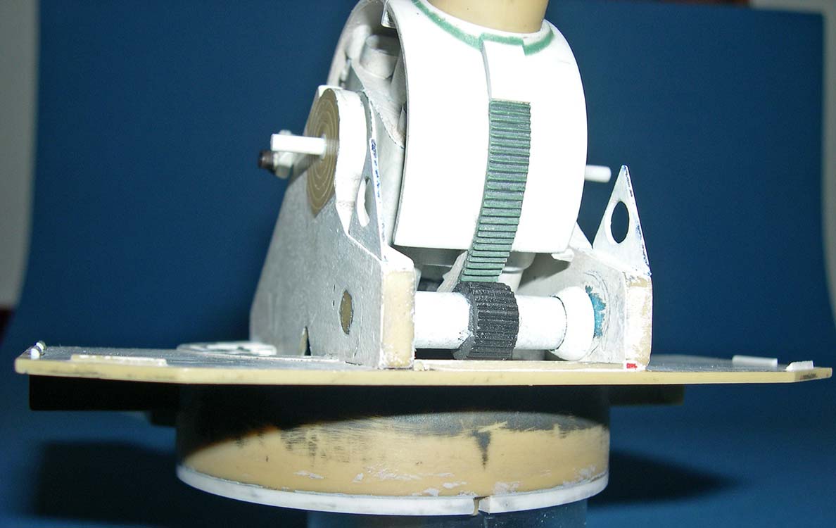
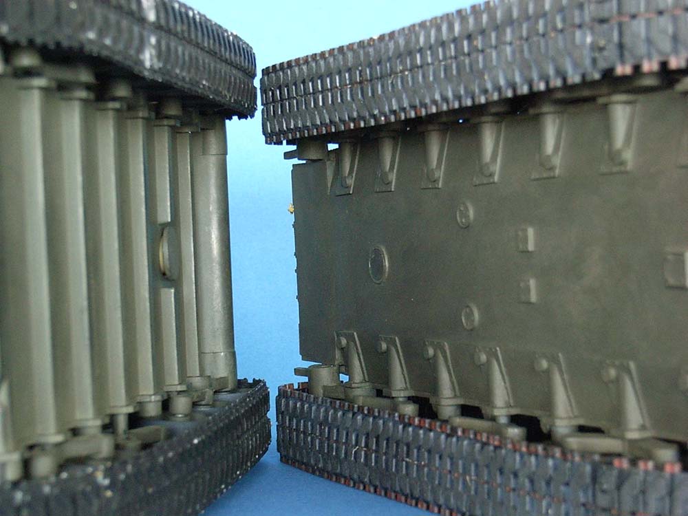
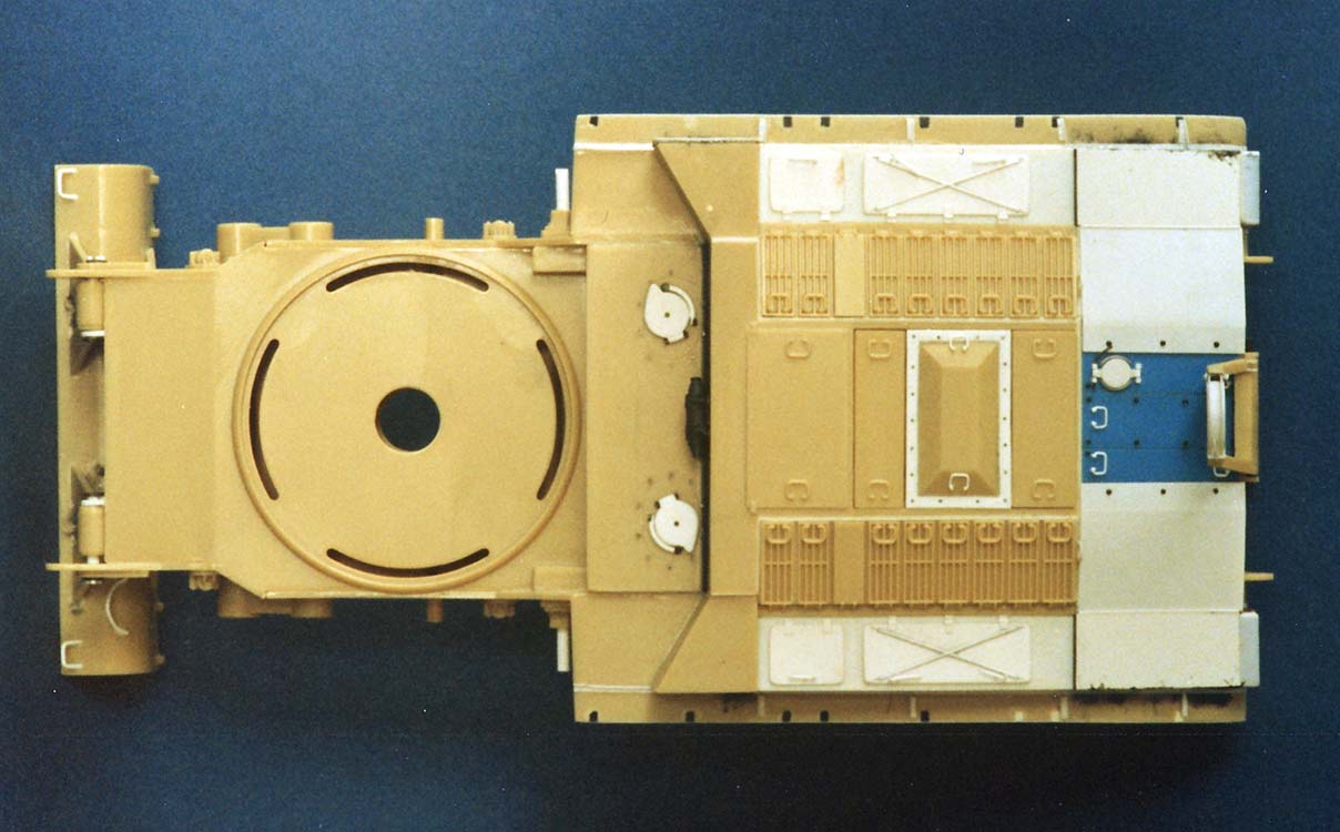 Construction started with the lower hull. This consisted of two flat side walls and the bottom plate with attached front and rear walls. The bottom was dead flat, too, and had six square "torsion bars" molded to its underside that protruded through the side walls -- some of them to the gap between the roadwheel halves, the others just a little more than necessary to act as axles for the road wheel bogies. Yeah, BOGIES, like on a Sherman -- see now why I recommend starting out with a decent hull? On the other hand, this system makes an excellently movable model suspension, and as the road wheels are large enough to completely hide the bogie arms, I just shortened the "torsion bars" to really look like such and left it at that. I cut off the molded-on guard wheels in front of the first road wheels and installed them on their own arms, again not bothering about the fact that, in reality, they're mounted to forward extensions of the first road wheel arms, pushing the track away from the hull when these road wheels go up, to prevent bellying.
For the hull bottom, I cemented pieces of 1 mm sheet onto 2x2 mm strips between the "torsion bars" down the hull center and others to the sides. The entire bottom was then covered with one piece of 0.5 mm sheet with cutouts for the torsion bars. These were hidden under pieces of drinking straw on 0.5 mm plates, and short pieces of sprue added as torsion bar anchors. The trailing idler "axle housing" (!) was removed and the idler swing arms received bump stop extensions. A few added service opening covers made the model presentable even raised on its spade above a mirror.
 After rounding the sharp bends in the front wall, front and rear of the hull were detailed, volute spring stops for the trailing idler wheels added, and the wheels installed after they received resin inserts for their inner halves (note that the trailing idlers are road wheels with larger hubs). The kit tracks were disgusting, but when I started out, I didn't have anything to replace them, so I just improved the kit drivers. Years later, I found AFV Club's M88A1 vinyl tracks to fit the model like a charm; they're a trifle too wide, but as most service photos show these guns without sand shields, they could be used. Sprockets for them were modified from those of the ancient Tamiya M4A3E8 or its Academy clone.
Long after I took the photos, I replaced the vinyl with AFV Club's M48 indy link tracks.
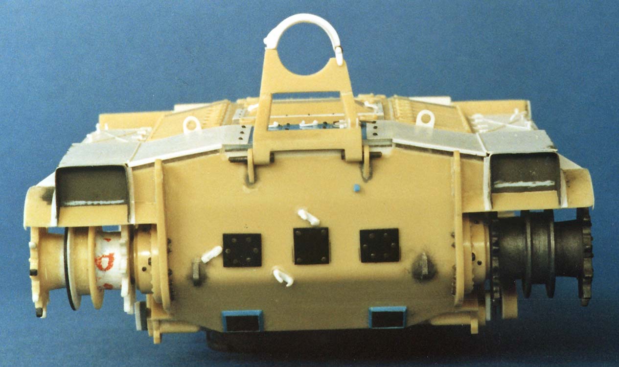
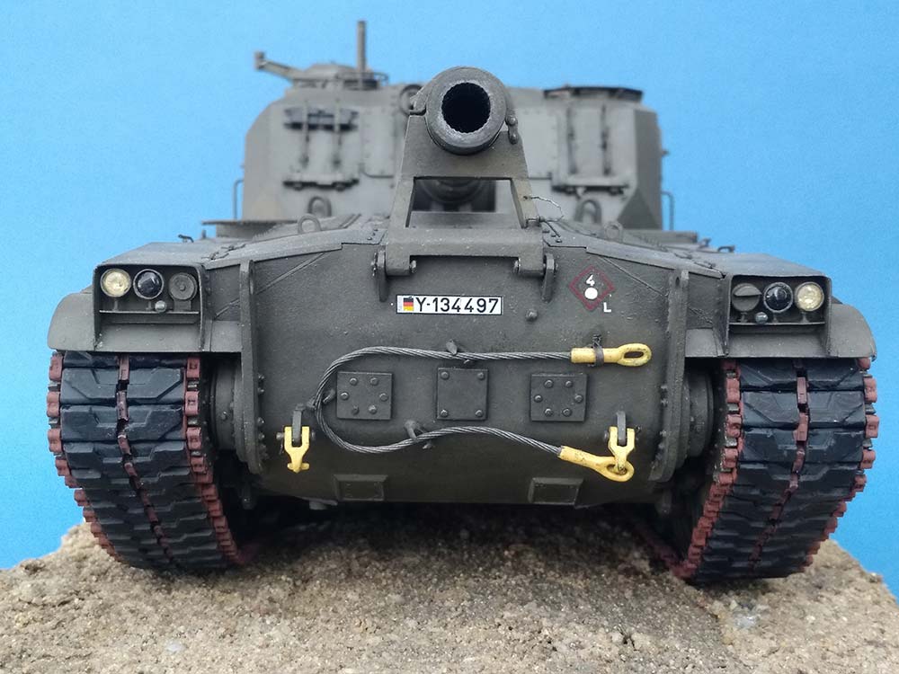
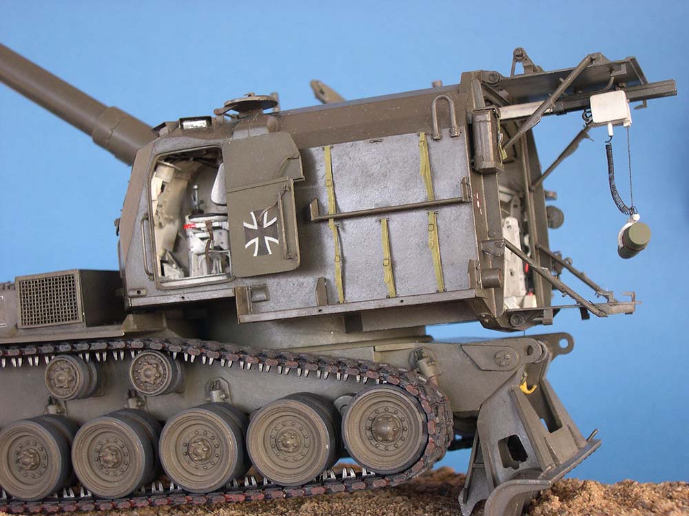
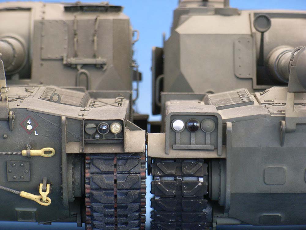
The upper hull was something else. It had the center engine covers lower than the lateral louvers, which gave a wrong angle to all the engine deck; the stowage boxes had rounded corners, the headlights were flat, you could see through the air intake and exhaust openings -- in other words, the whole thing had to be sawed apart in order to use some of the parts by cementing them back together at different angles. The transmission covers needed scratchbuilt replacements and details added before everything eventually resembled the prototype. Engine exhaust pipe and generator muffler were placed on the right, the wire mesh here was left off to show them. Two volute spring turret traverse stops were mounted against the engine rear wall and fuel tank fillers scribed into the hull top below the turret front, near the tracks.
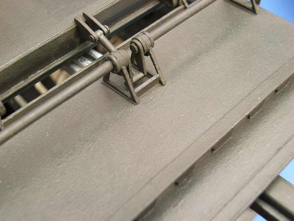
The spade had its suspension braces boxed in and connected by a center brace; three pieces of stretched sprue were cemented on as eyes for the lifting rope hook and the latches that hold the spade in the traveling position. One detail I didn't find a tool for: All braces of the spade shovel have a lentil-shaped hole to allow water to run out in the march position.
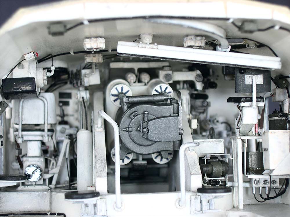
Turret
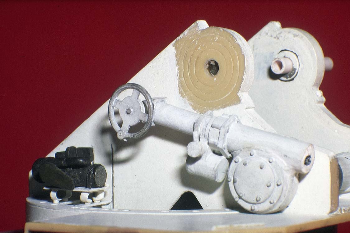
There were only a few turret parts that could be used as a basis for corrections: The floor had the running boards sawed off and its few molded-on details removed except for the "tub" around the gun and the two ridges on the tub bottom; the trunnion supports, too, had their details removed. The side and rear walls were discarded along with all doors; the roof with the attached front wall seemed too involved to scratchbuild (ha!), so it was saved along with the "frame" around the gun opening. For the same reason, the two rearmost parts of the gun and the commander's cupola including its hatch were kept; everything else went into the scrap box.
On the OTB model, the turret rear wall below the floor touches the outer spade hinges, canting the turret forward when it is traversed. To prevent this on the corrected model, the turret socket had 2 mm added. Removing the details from the turret floor had left holes that were filled. The trunnion supports had plastic sheet cemented to their inner faces to make them "solid" and received triangular cutouts at their bases. They were then modified so they could be placed closer together, onto the ridges on the "tub" bottom. A perforated ring from thin sheet was cemented onto the tub's thinned rim and into slots in the trunnion supports.
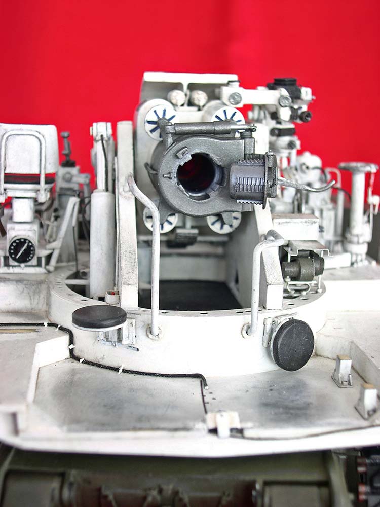
 The kit gun's shape was far from any resemblance to the prototype -- especially, neither the M53's nor the M55's gun ever had a center band or a muzzle brake.
 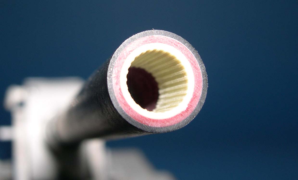 The correct outer diameter of the front part was found as clear vinyl tubing. It was stiffened with an empty felt-tipped pen and received some rifling at the muzzle end from a resin barrel generously donated by New Connection's Lutz Fellmuth. The forward section of the recoil tube is the reworked kit part; the gun shield molded to it was removed, as it wasn't really circular. The recoil tube rear part began life as a cigarette lighter; it was mounted into the kit's breech/recoil system skeleton which had been freed of the breech and recoil cylinder imitations. The latter were reconstructed from small ball pens (the tips of which started new careers as projectiles). That these cylinders should form a square around the tube, not a rectangle, became painfully obvious (too late, of course) when the new gun shield didn't leave much room at top and bottom of the assembly.
 A new breech was scratchbuilt (with opening lever from the kit), its projectile chamber wrapped with lead foil counterbalance and a drinking straw bore inserted. Replenisher cylinders atop the recoil assembly are straws again, the elbow-type direct sight telescope is plastic tubing and bits and pieces. The fifth attempt at a new, asymmetric, gun shield was fashioned from laminated plastic sheet and had a vision hole for the direct sight telescope drilled in. To its bottom, an elevation gear rack from epoxy putty was cemented, and a scratchbuilt elevation gear axle with cogwheel whittled from plastic tube was mounted between the trunnion supports. To the shield's outside, a new mantlet cover spacer from a piece of aluminum tubing and plastic rod was cemented in the telescope's line of sight.
 Two guard rails were bent from copper wire and installed to the trunnion supports and the tub. Next to them, folding loaders' seats were mounted, and a third one built for the left side wall, behind the driver. The discarded hydraulic pump was pardoned and reworked, elevation and traverse drives were scratchbuilt together with the traverse gear box and the azimuth indicator on its top. The
 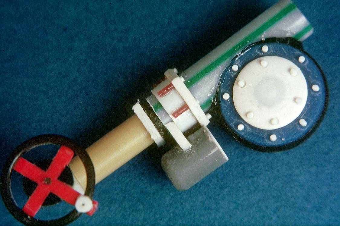 gear box found its place in the "tub", outside of the right trunnion support, and was connected to the manual traverse column by means of a drive shaft on the floor with a sheet plastic protector. The hydraulic pump was cemented across the right front corner and the elevating drive housing to the right trunnion support. The rather elaborate panoramic telescope mount with its working elevation indicator was also cemented to this part and connected to the traverse gear box by a drive shaft with (non-operational) universal joints. Brass wire and stretched black vinyl sprue provided the hydraulic lines between the pump and the manual and power elevation and traverse controls. The firing pedal pedestal was placed between the traverse connecting shaft and the hydraulic pump.
 On the left trunnion support, a movable equilibrator system from different pieces of styrene tubes and other bits and pieces was installed. For the "chromed" hydraulic rods, nowadays I would use pieces of telescoping transistor radio antennas, but way back then I had the following idea:
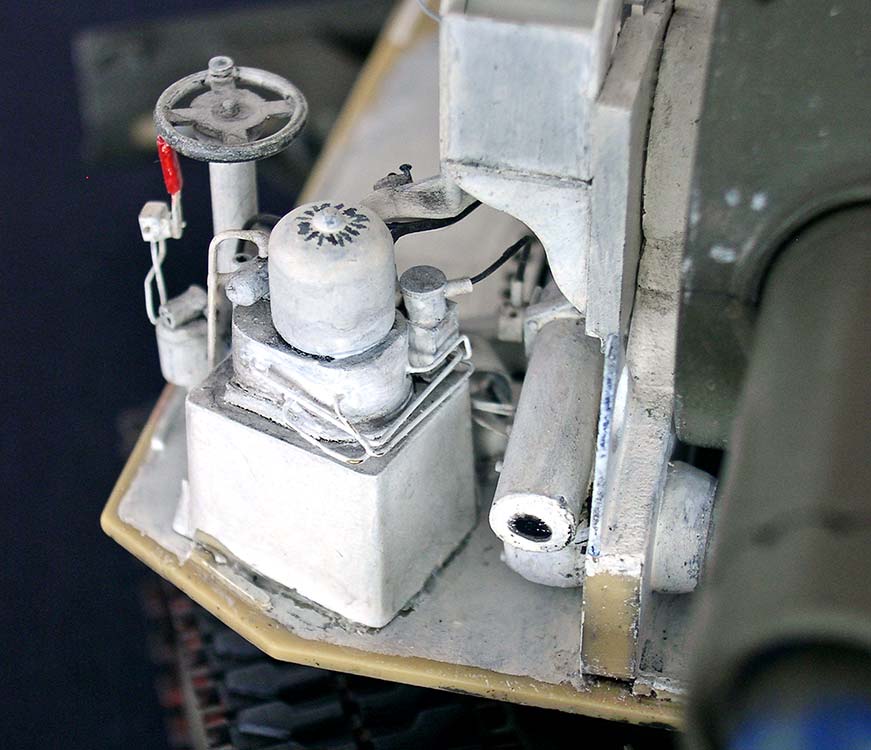
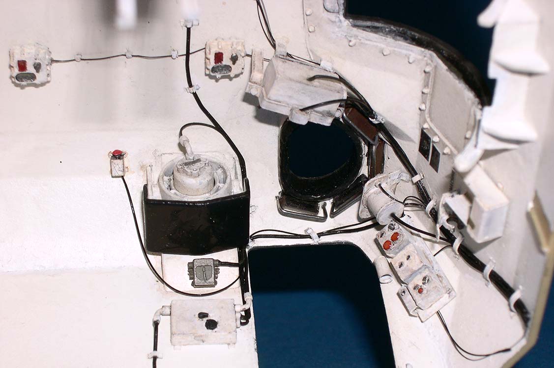
 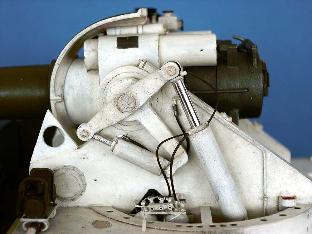 Some candies and especially chewing gum packs have multi-layered wraps, with one of those layers being a very thin aluminum foil. This is joined to the others with a sort of wax and can be separated from the rest by very gently and slowly pulling on one corner. If necessary, another smoothe-out on a metal or glass surface will prepare the foil for cutting into shape and application with a suitable adhesive, taking care that the seam is out of sight as far as possible. As can be seen on the rod on the left, that doesn't always come out completely wrinkle-free, but it's a practical and low cost method.. At the turret front, a personnel heater was installed (with a second one built at this time to be mounted behind the traverse gear box). For the walls above and to the left of it, speedometer and different control boxes were prepared. A driving control column was set between the new driver's seat base and the gun. The instrument and switch panel hangs from the ceiling above it.
 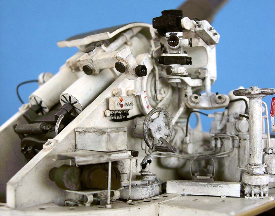 Continuing on the left, an "oddment rack" and the powder containers rack were set against the side wall (note that the latter was made after the photos in the TM -- the standardized version was lower, with a horizontal top, but I noticed that too late to bother). A rifle rack from sheet plastic is the rearmost item here.
 The kit didn't provide a gunner's seat, while those for driver and commander were incorrect, so three identical seat supports were built. Driver's and gunner's seat shells were thermo-formed from sheet and received upholstery from tissue paper soaked in and covered with gouache-blackened white glue; their seat rests were made the same way. The commander's seat upholstery was cut from different pieces of black plastic plate.
 Behind the traverse gear box, two braces were installed between the perforated tub ring and the trunnion support to carry the second heater. Instead of a wire mesh protector like the driver's one, this one has a sheet metal "roof" that stands on four wire rods, right below the stowage box for the panoramic telescope. Both heaters have exhaust pipes leading into the turret side walls. The commander's seat was cemented on a pedestal mounted to the right turret wall and standing on two supports; a platform hanging underneath carries the radio system, the intercom control box is on the wall beside the commander. Rearmost on the right is the
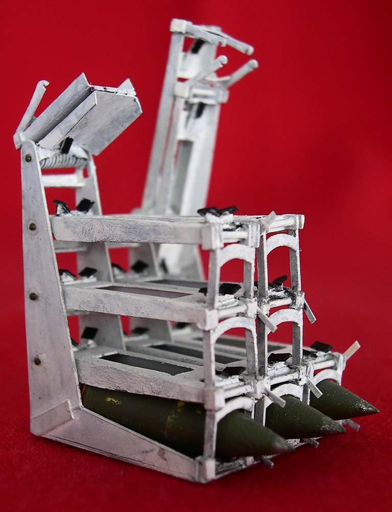
  projectile rack (composed of more than 200 individual pieces of plastic -- one of the places I really got carried away). Between it and the commander's pedestal, there is another rack mounted to the turret wall for stowage of the commander's hatch periscope.
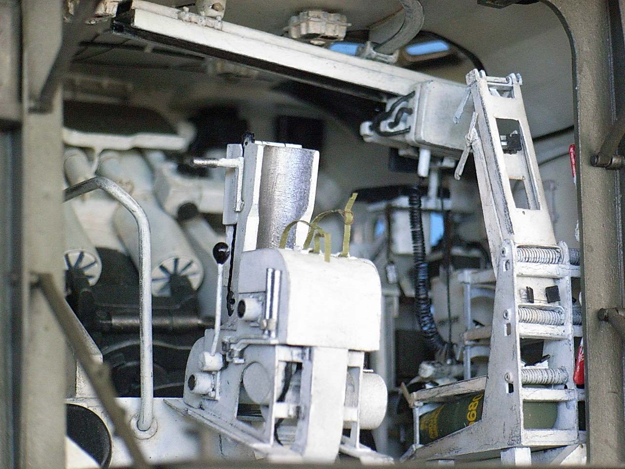
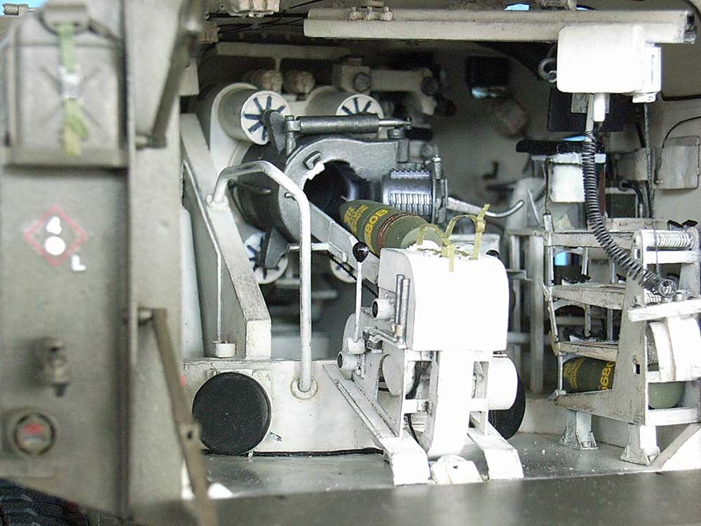
The power rammer, too, was completely scratchbuilt, with cranks for manual operation on the left and shirt pin operating handles. To find out the correct length for the folding projectile trough, I built it in a working mode, which gave me the excuse (as if I needed one!) to make the breech movable, too. On the prototype, the rammer motor also drives the spade hoist cable drum, hence the pulley in the turret floor behind it.
 After preparing most of the innards of the turret, it had to be enclosed. The kit front wall was too low, as the rhombic plate on the gunner's side has a pointed upper end which meets with one of the bends in the roof. This was corrected by cementing on and beveling a piece of plastic sheet. As both sides are equally high, the multi-angled area between the gun and the
 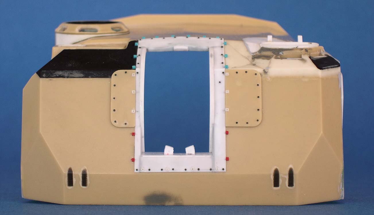 driver's hatch also had to be built up; this entailed changes in the area above the driver's door and behind his hatch plus the fan housing. Lack of suitable photographic reference held me up here for more than a year, until I finally decided for the most likely guesswork construction, raising the lintel. While in this area, I also made a new driver's hatch and periscope covers. In hindsight, this hatch and its opening might have been enlarged somewhat.
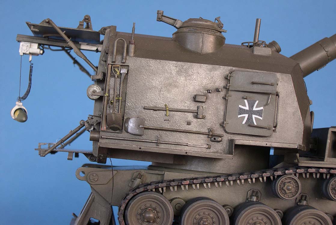
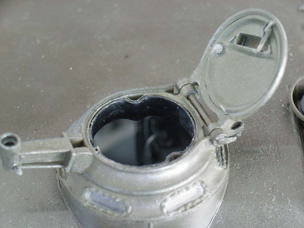
 The rather conical "pulpit" beneath the commander's cupola was replaced by a roll of sheet, the vision blocks were drilled out and replaced by pieces of 2 mm clear styrene. (Out of curiosity, I also tried this material plus chrome foil for functioning driver's and gunner's periscopes -- and it worked !) The cupola, its hatch and the MG mounting brace were corrected or replaced by scratchbuilt items before the whole affair could be installed in a rotating fashion. Crash pads were fashioned from tissue paper and diluted white glue that had been tinted with black gouache.
The gun opening was made narrower by cementing in the vertical parts of the kit's frame, reduced to the front wall's thickness and without their outside "ears". An additional 2 mm strip was cemented to the left side to give the opening the correct  width for the replacement gun shield. Circle segments cut from 1 mm sheet were cemented to 0.3 mm sheet and then into the sides to overlap the shield, and the openings above and below it were lined with the same thin sheet. The kit frame "ears" were sanded considerably thinner and had their fastening bolts replaced by more realistic items, while the areas covered by them were outlined as openings on the inside -- after all, the gun can't be extracted without its trunnions.
The flexible part of a drinking straw became the "rubber" protection between the inside parts of the panoramic telescope and the turret roof, three plastic disks surround the lower end of the outer part, which is a piece of styrene tubing with some clear acetate at its drilled out top front.
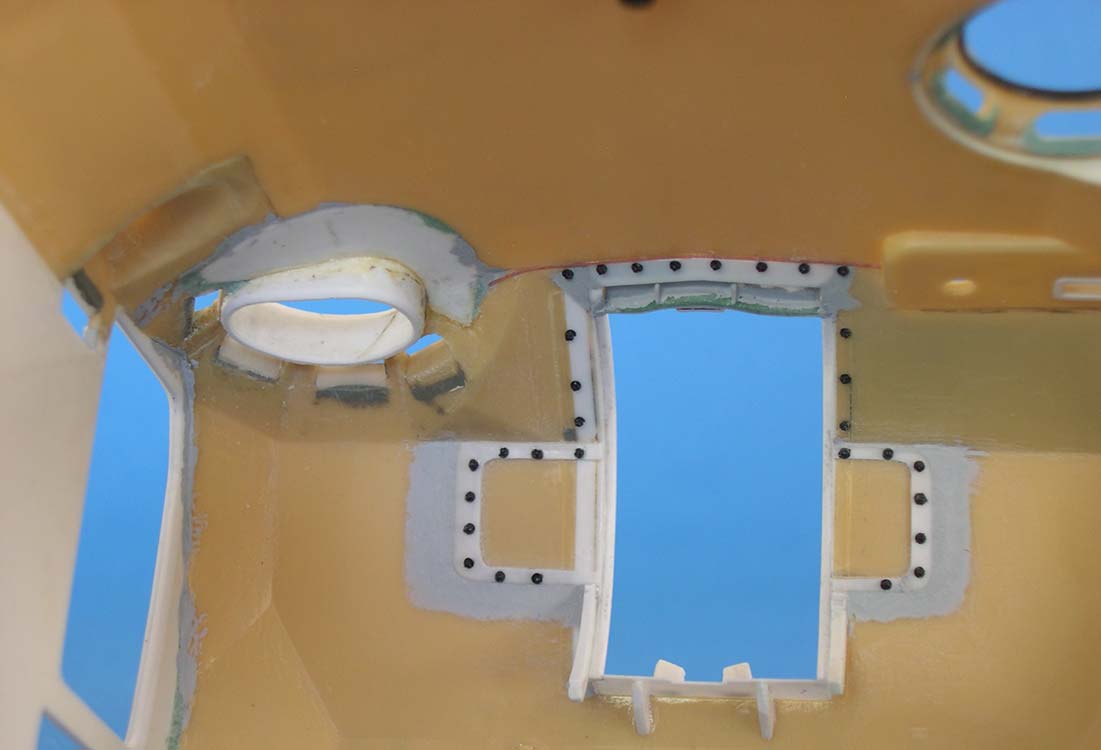
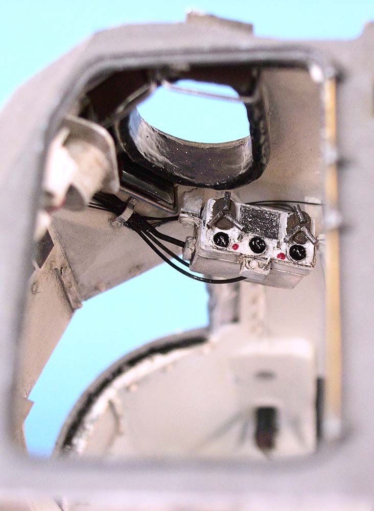
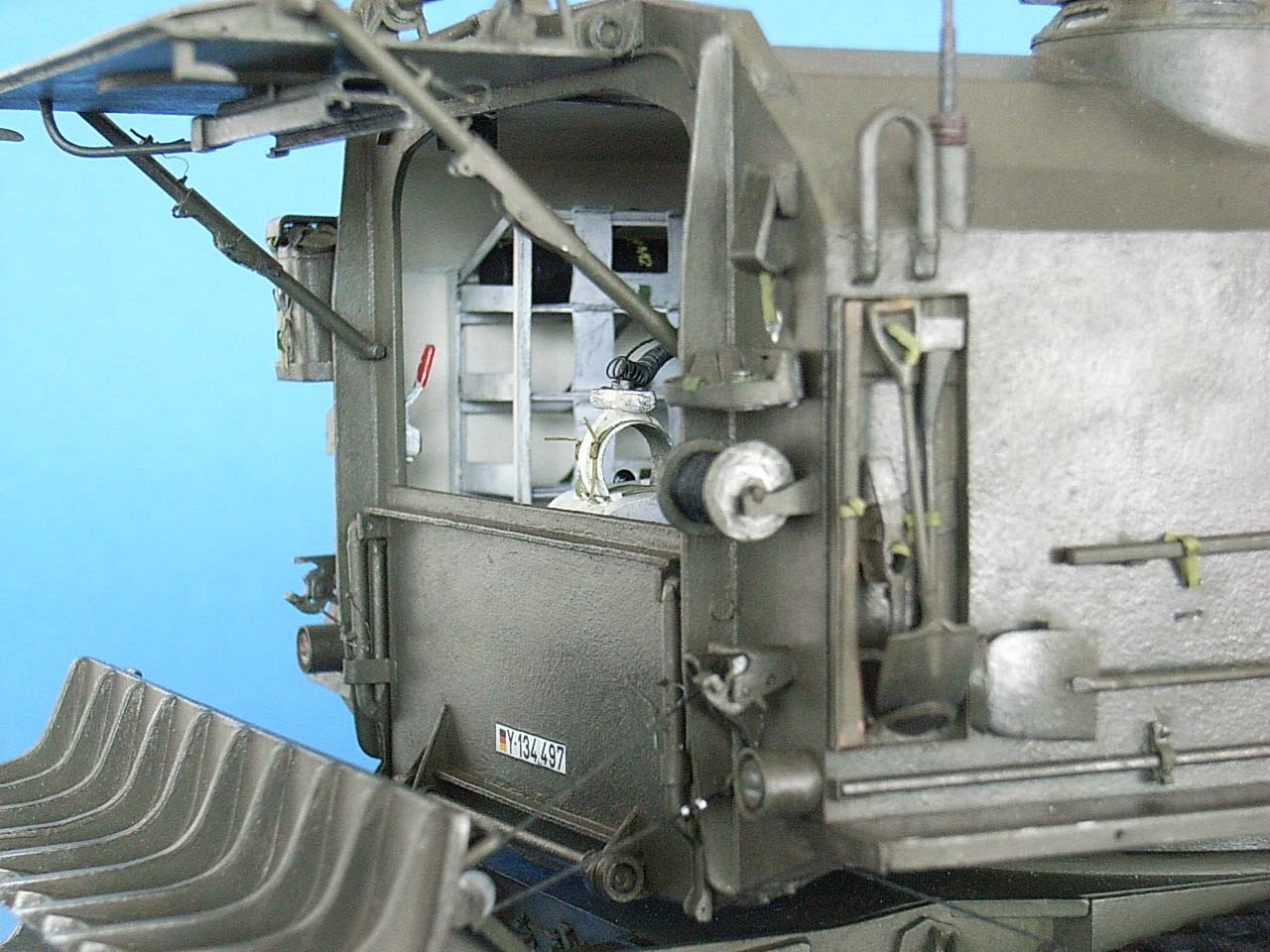
 New turret side walls were cut from 1 mm sheet and had the door openings cut in, surrounded by splash rails from plastic strip. The turret fan was fashioned from the end of a sewing thread spool with a piece of sprue cemented inside. A crash pad covered with black PVA glue was set around it and a new air duct to the side wall constructed, with a "turret accessories panel" to go beneath it. Other instruments, switches, and switch panels were arranged around the driver's position and wherever else they belonged, also dome lights and headphone control boxes that had been cast in resin after self-constructed masters. "Cabling" all these correctly (or should I say, excessively) with wire solder and stretched black sprue took a good deal of time, too. The two-part side doors were made from 0.5 mm sheet and received working plastic hinges and copper wire locking handles.
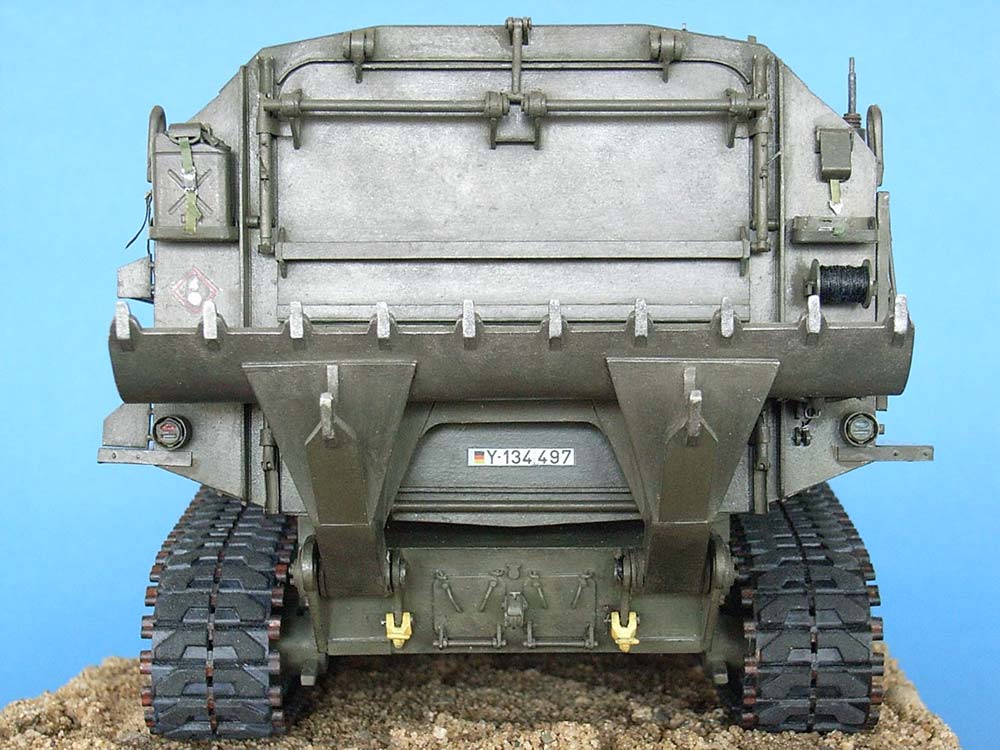
 The ammunition hoist tracks were constructed from 7 mm wide strips of 0.5 mm sheet, below which two 1.5 mm Plastruct channels were cemented. A 4 mm channel was cemented along the centerline on the top side. The front track is suspended from the roof and moves in a quarter circle on a T-track, but can also be slid longitudinally to join it to the rear track. The front end of the rear track has its swivel point in the center of the upper rear door; its other end glides on an L-track to stow, pointing to the right. The hoist itself was built from bits and pieces and was left sliding in its tracks, with the projectile clamp formed from a horseshoe of 1.5 mm sheet with a collar of thin sheet cemented inside and a four-button control handle of 10 x 2 x 2 mm. The hoist cable is thread, the coiled electrical line is stretched black sprue.
 The turret rear wall was also replaced with one from 1 mm sheet. A rain gutter was added above its opening, and the doors replaced with ones from 0.5 mm sheet with added reinforcing braces that weren't all found on the kit parts. The hinges for the lower door presented an unexpected problem: Reference photos showed that the closed door reaches down very far, which would have required operable hinges that stood out much more than those on the prototype. Which once again goes to show that making details movable can also help to find out their shape. To give everything the correct looks, I eventually had to cut a 1.5 mm strip off the bottom of the
  (kit part dimensioned) rear wall. So much for the need to raise the turret socket, was my first thought, but another scrutiny of all available photos showed that the altered distance between hull top and turret floor at least isn't conspicuously incorrect; a 1 mm raise probably would've been perfect. Oh, well. -- Construction of the upper door's movable torsion bar link and the four folding support braces was fun, too -- especially establishing the latter's correct length to find the hinge points on the turret wall was time-consuming, to say the least (I'm geometry challenged, so it was all trial and error).
 While adding the water can racks, communication wire reel plus holders and spade hoist rope outlet offered no problems, the "latches" that hold the spade in the traveling position were the most challenging detail of all. On the prototype, they're operated by "cable releases" from the inside – but where would I find a 1/32 scale operator? Eventually, I came up with the idea of substituting the hinge axle of these contraptions (that actually look like the pintle on Tamiya's ancient M 41) with a piece of 0.5 x 1.5 mm plastic strip mounted horizontally: the movable part then had a "keyhole" cut in so that it can be rotated when it's pulled out and is arrested in the pushed-in position. (The same principle was applied to arrest the rear ammo hoist track in the stowed position on the upper door.)
| Painting/Weathering |
Painting was done as I went along -- as I didn't work with an airbrush plus wanted to keep the details functional, all the little sub assemblies to go into the turret had to be painted separately, before being installed.
They all received a base coat of Tamiya acrylic Metallic Grey and were then finished with Revell Matt White. An oil paint wash helped to get a somewhat uniform color inside the turret, with some pencil scratches and drybrushed silver paint for highlights.
The gun bore was painted with tobacco pipe cleaners dipped into Humbrol Metal Cote Polished Steel. The breech exterior was painted Humbrol # 53 "old version" (which meanwhile changed its name from Gun Metal to Metallic Grey and also became glossy); this also served as primer for all outside surfaces. These were then painted Revell # 46, NATO Olive.
Markings were custom printed by a modeling friend on decal paper and brought to the model with Micro Sol and Micro Set. Painting and (painting skills requiring) figures are the two things in modeling that I plain hate, so I left it at that.
| Conclusion |
And so, what more than once appeared to be a never-ending story, came to an end after all.
| Price / Value: | ***** | Fitting: | ***** |
| Detailing: | ***** | Skill level: | ***** |
 |
 |
 |
 |
 |
 |
 |
 |
 |
 |
 |
 |
 |
 |
 |
References:
- http://www.toadmanstankpictures.com/m53 35 Photos -- if only I'd had these earlier !
- http://www.globalsecurity.org/military/systems/ground/m55-8.htm 12 photos plus one of ROCO model
- http://www.mil-mod.nl/html/ in "Photo Gallery, TM Photos" und "Construction Articles"
- http://afvdb.50megs.com/USA/8insphm55.html Technical data, 1 photo
- http://www.battletanks.com ""Photogallery / USA 2" photos of M 53 and M 55
© 09/2018 Peter Schweisthal
14561 readers of this build report since 27.09.2018