|
|
 |
| The Original |
The Ben-Hur trailer was the nickname for the World War II U.S. Army trailer (1-ton payload, single axle). The nickname originates from the primary manufacturer, Ben-Hur Mfg. Co., although many other companies produced it between 1941 and 1945. The standard cargo trailer had the Odnance Number G518. Specialized versions were also produced. The 1-ton trailers were designed to tow vehicles with a payload capacity of 3⁄4 tons and over, such as the Dodge WC-series truck, as well as 1 1⁄2-ton 4x4 trucks and 2 1⁄2-ton 6x6 trucks such as the Chevrolet G506 and the commonly used GMC CCKW trucks. With a total of 259,064 units produced, the G518 trailers were among the most widely built and used models by the Allies.
| The kit |
This kit surpassed whatever you would expect to get for a small model: 55 or so parts from plastic, 29 from PE, plus a piece of overscale metal chain come in the box, and you're expected to contribute four pieces of different thin wire. Some of the plastic parts are 1x2x1mm, the dozen brass tiedowns 1.5x0.6mm

| The build |
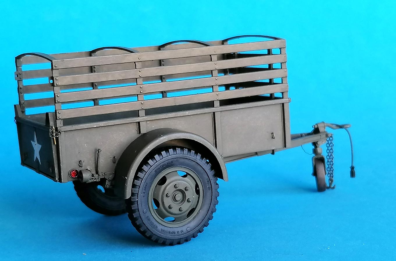
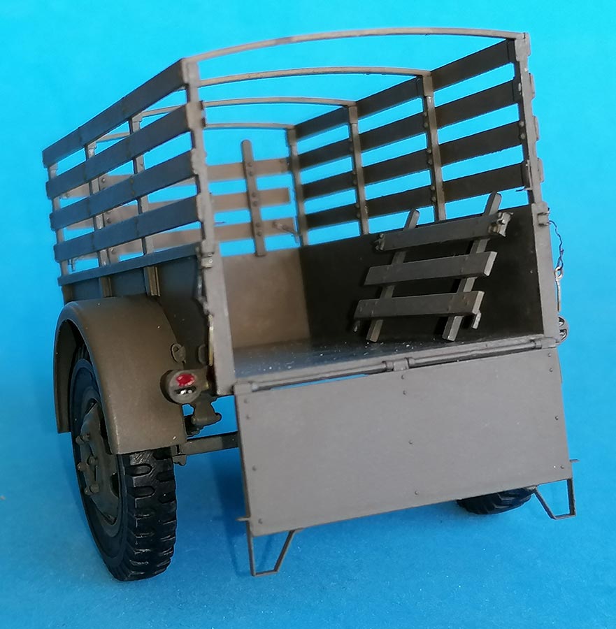
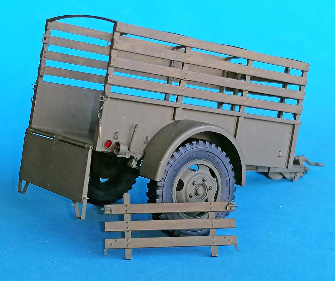
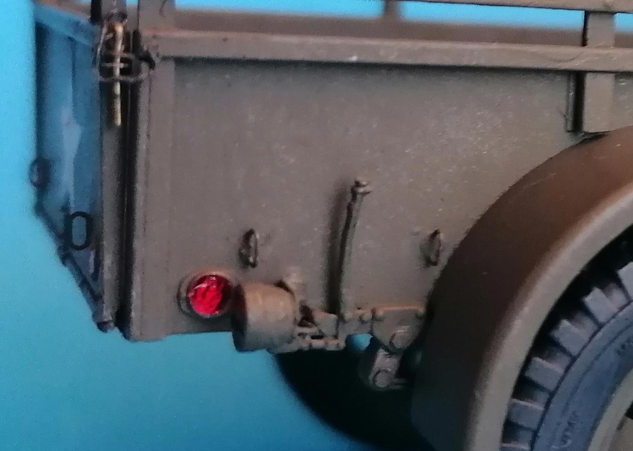 The instructions have you start with the sides of the load bed. You get a choice of adding stakes with wooden slats, which I did. This led to the installation of a number of PE parts; thankfully, the PE fret has clear vinyl sheets on front and back, which minimizes the risk of sending parts flying when cutting them off. The taillights mount to PE parts, but the lights are wrong, as in most all kits of US-built vehicles from 1941 thru the Vietnam era; I had correct resin copies (different for left and right side) that I installed instead, plus "electrical leads" from stretched sprue.
The 12 tiny PE tiedown eyes around the load bed were left off for the time being, as some of them inevitably would be knocked off during further handling.
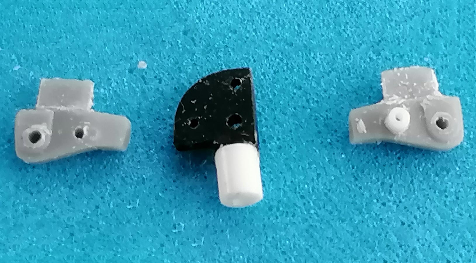
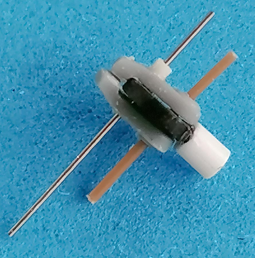
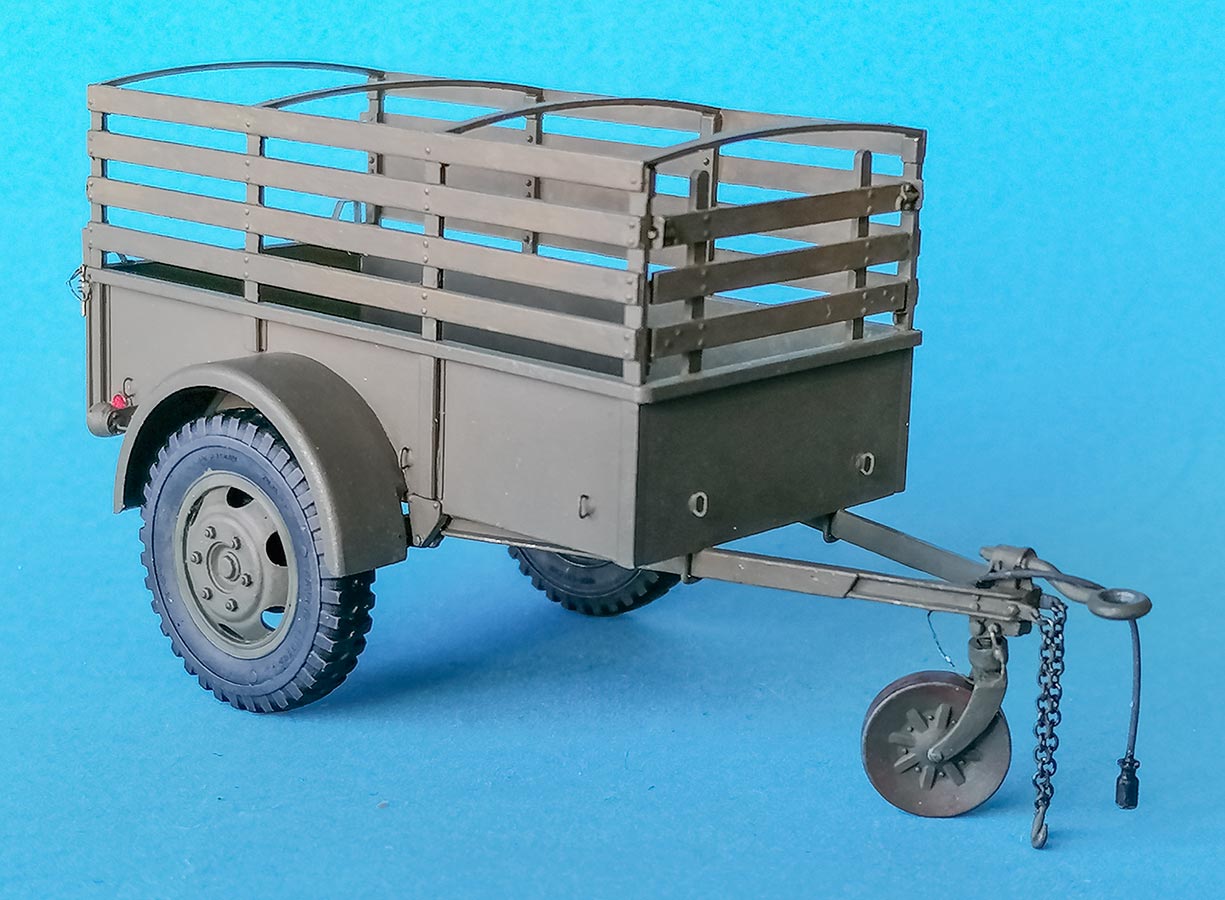
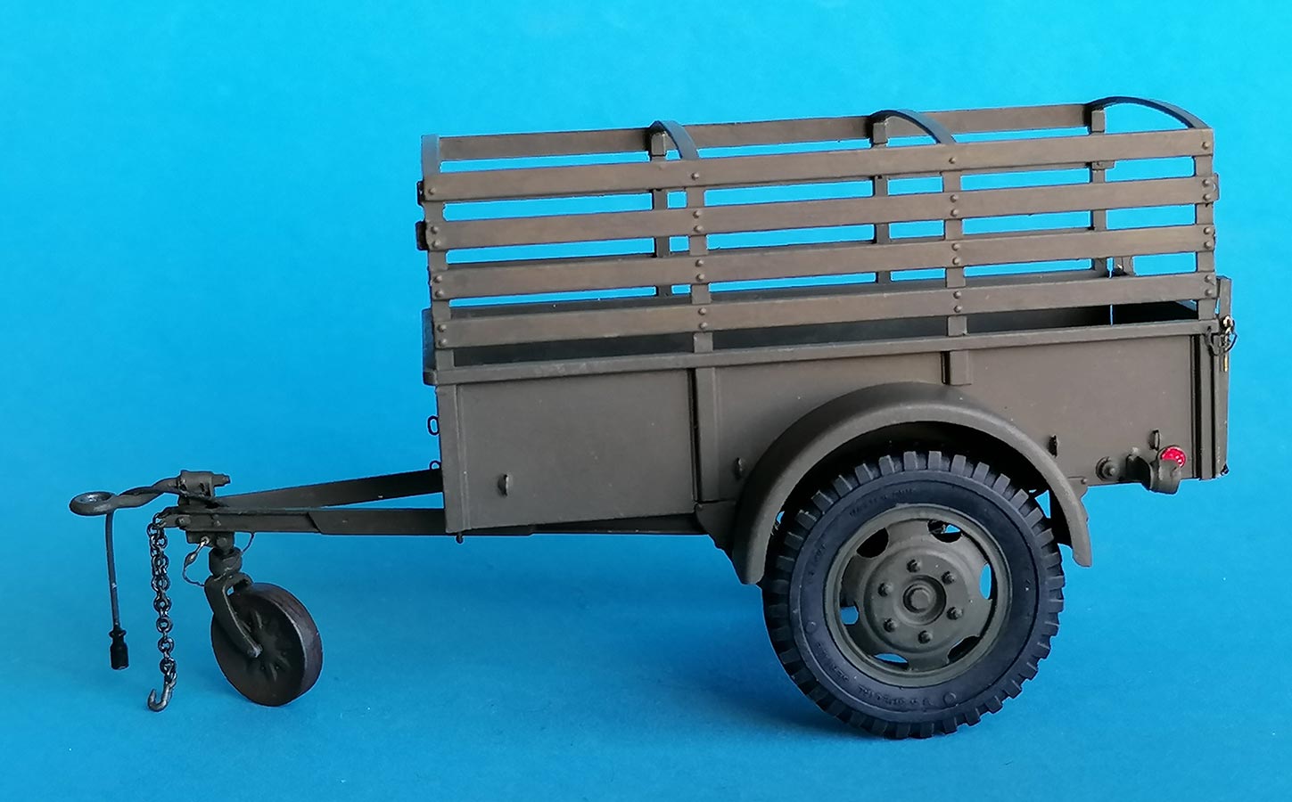
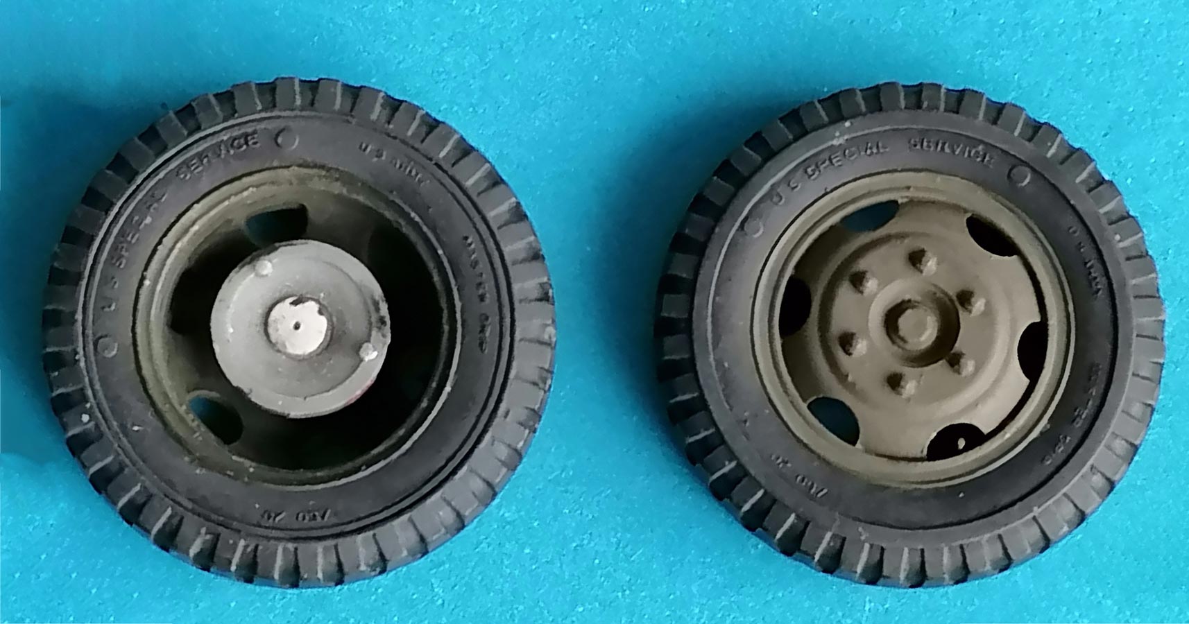 Next came the wheels. Making them turnable was so easy that I couldn't pass that chance: their axle pins were lengthened with punched-out slices of styrene sheet, and larger diameter slices were prepared to be cemented to them before joining parts Bm5 to the other halves of the brake drums. And, of course, the wheels must receive valve stems from 0.3mm brass wire. With all the tiny pieces, plastic and PE, that MiniArt packed into this little kit, I find it amazing that they didn't include these.
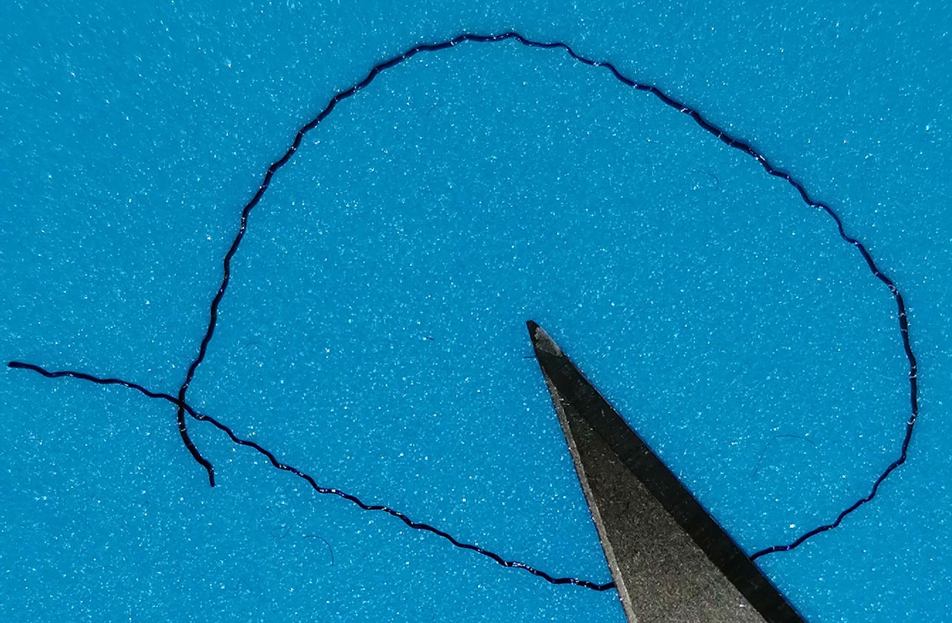 Before joining the side walls to the bottom of load bed Ce15, a few shallow sink lines in that part were puttied; the rest of the kit didn't need any. The tailgate's outer hinges were drilled through with 0.3mm, as were the outer hinge parts on the load bed; pieces of stretched sprue made this operable. The locating marks for handles PE2 on the top of the tailgate were so inconspicuous that I had cleaned them away before I had realized their existence – gotta memorize the instructions before you begin building! The kit's PE tail gate locking pins had, of course, unrealistic PE securing chains, so I bent pins from 0.3mm brass wire and secured them with "latex chain" from the top of black panty hose.
 On the underside, you have to come up with pieces of wire to represent the parking brake lines; this area was the most difficult one for me. Distribution device Ce8 and brake line guide Ce6 should have their contact points to the respective wires slightly drilled for easier mounting of the wires (for the straight one in the center, I took a piece of stretched sprue). I had to chamfer both parts on their cementing surfaces for a good fit. Instead of wire, I used thin solder for the lines leading to the brake drums and drilled their mounting holes in parts Bk12/13 through so I could securely superglue the solder before bending it to meet Ce6/8.
The instructions don't tell you, but the "axle" Bk10 has different locating pins for the brake drum plates Bk12/13, so you can either study the illustration under a microscope before mounting Bk10 (the pins have a "U"cross section and the straight surface is supposed to face the rear of the load bed) or ignore which drum part goes where and fix them as you get them to fit: the detail on them is mirrored and very subtle. Either way, mounting the brake drums with their brake lines is rather fiddly as the lines have to pass over the leaf springs to meet their operating mechanism. And as the cementing surfaces are very small, extreme care should be taken to create a strong bond.
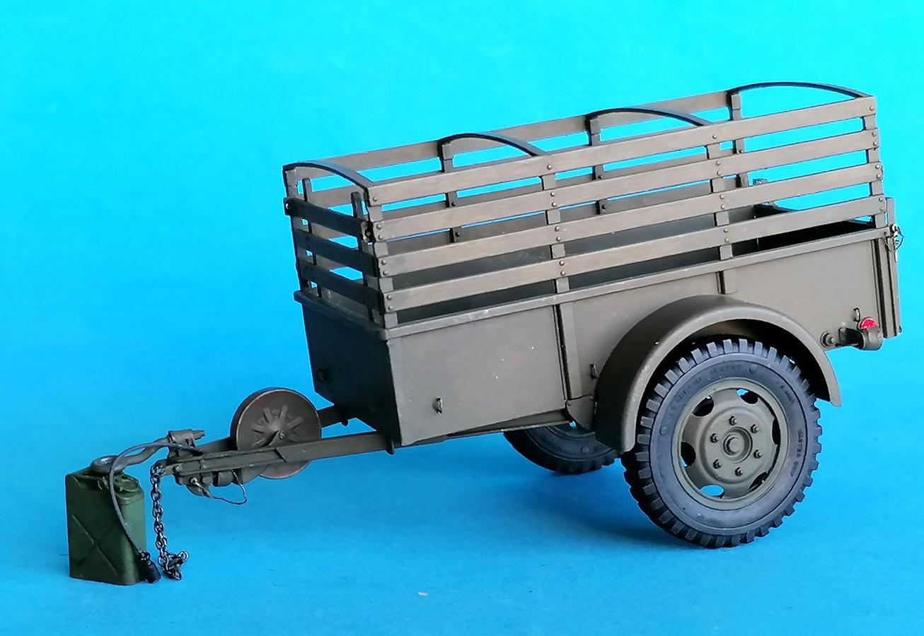
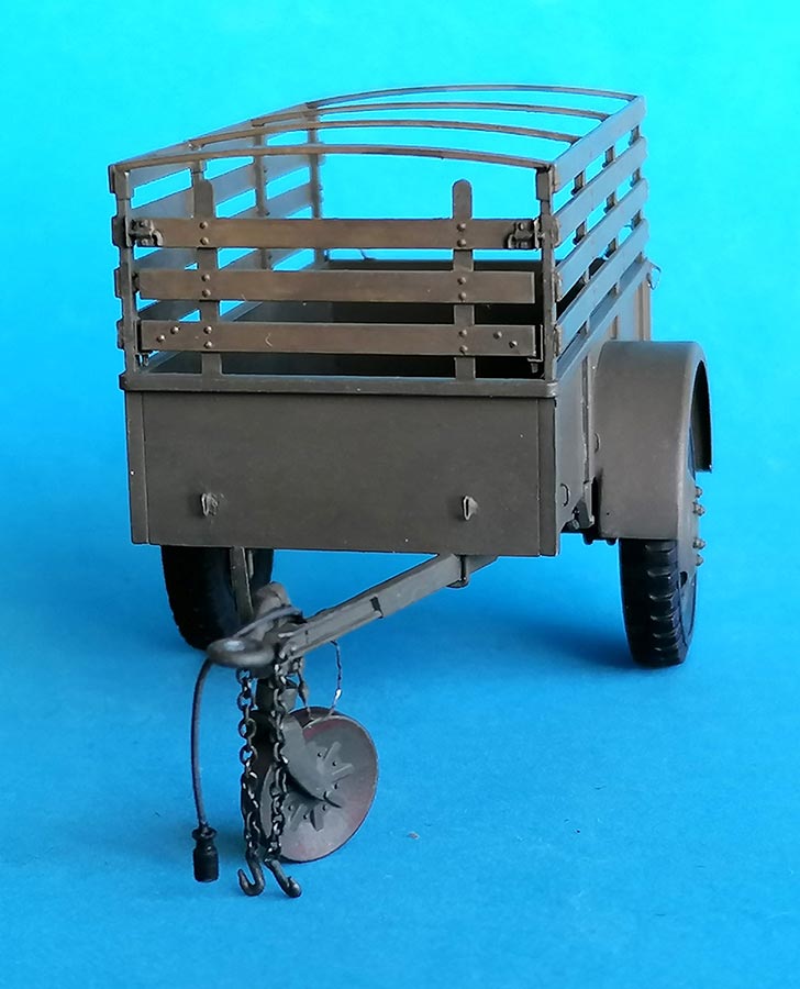
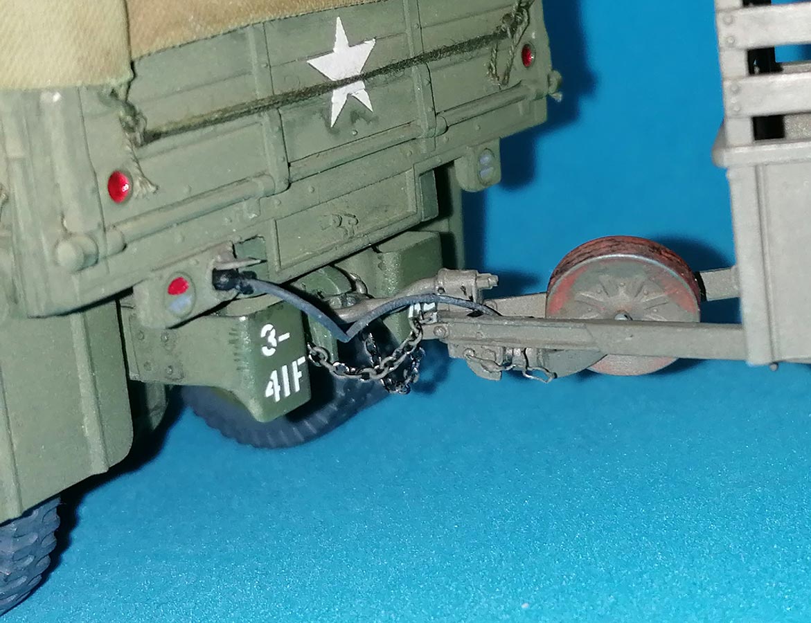
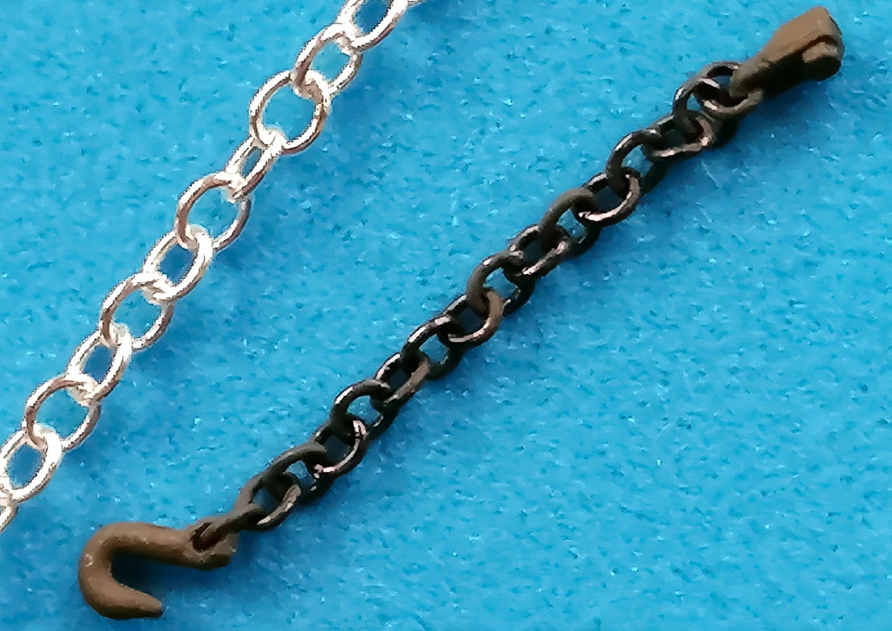 Why the two halves of the draw bar have to be installed with tiny clamps Ce3 is beyond me – those could easily have been molded to the bars. To my taste, the kit's trailer securing chain material was overscale, so I substituted finer chain from the ship modelers' range. Both the hooks and the mounting points on the draw bar were drilled through to realistically receive these chains.
 |
 |
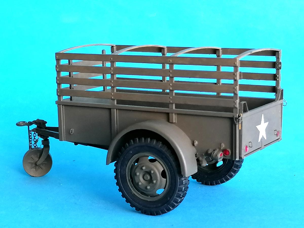
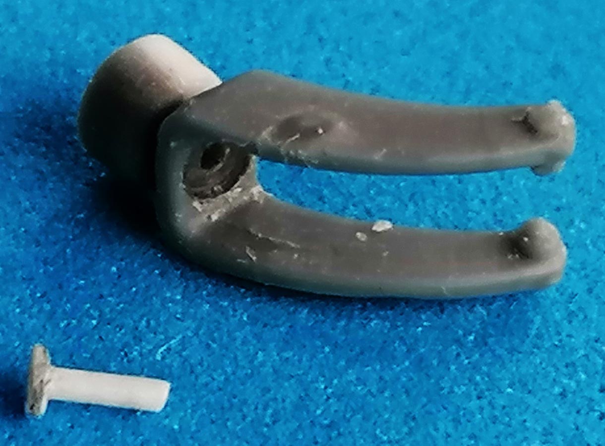 The "fork" of the landing wheel, Bk17, had its top drilled through and a 0.6mm axle pin was prepared by holding its end near a flame and then pushing the resulting "mushroom" onto a flat surface. The hole in the fork was widened on its underside so the axle pin's mushroom head could rotate in it. The half cylinder on the top of the fork was made into a full one by cementing on a piece of tubing to better guide the drilled-out lower end of Bk5's replacement; I've no idea whether that's correct.
 Several parts on sprue Bk are not being used for this model – it would've been nice if the instructions had told the modelers which ones, instead of having them scrutinize all build steps in search for hints where the parts might be needed. Eventually, I discarded parts Bk3,11,18.
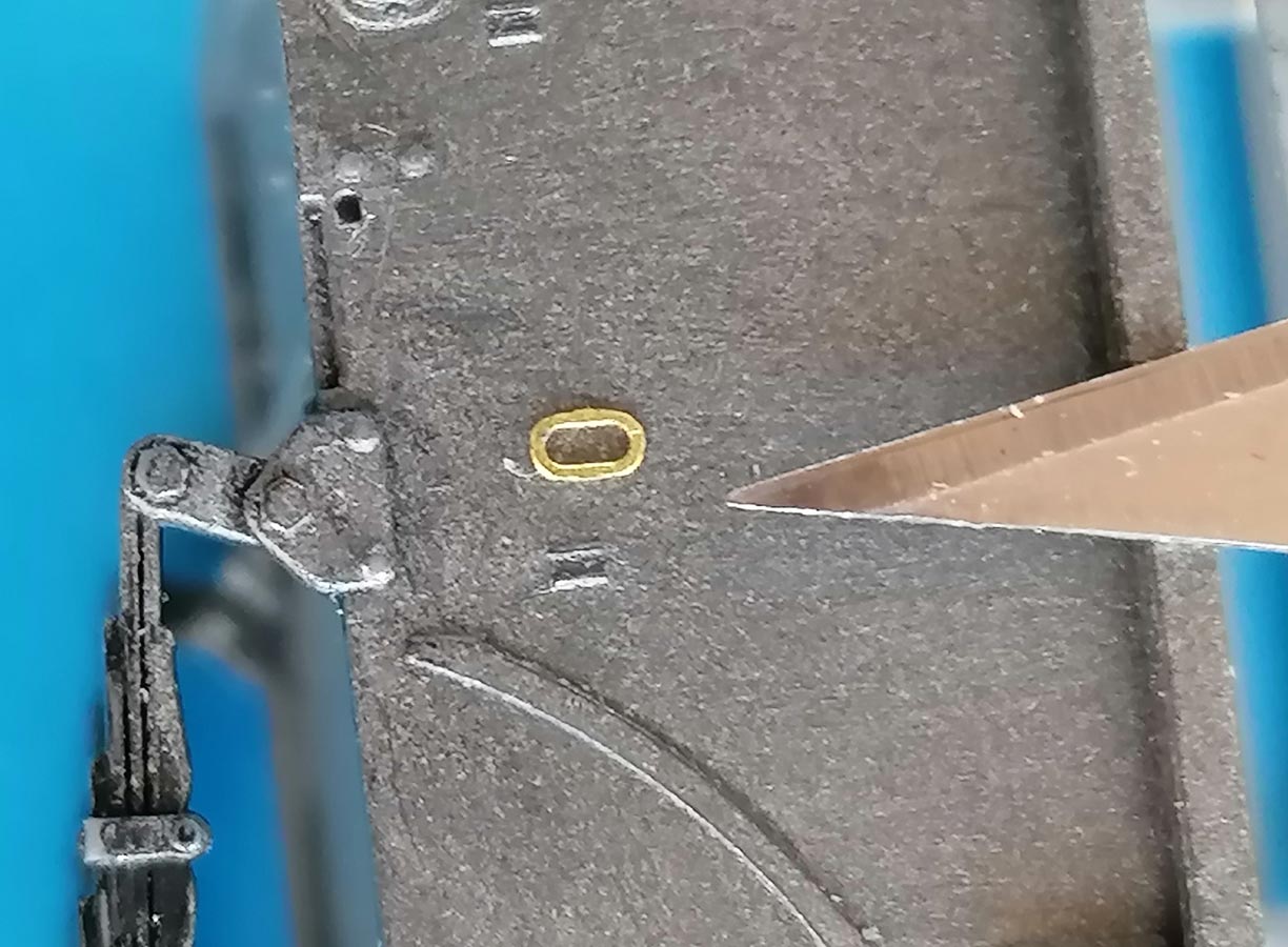
The 12 microscopic PE tiedown eyes all around the trailer are pure madness, and it took me many attempts to finally find a method to mount them: A minuscule amount of gel superglue was applied between the marking lines to give a temporary hold for the part which was then placed and affixed first with normal superglue and finally secured with 2 part epoxy glue.
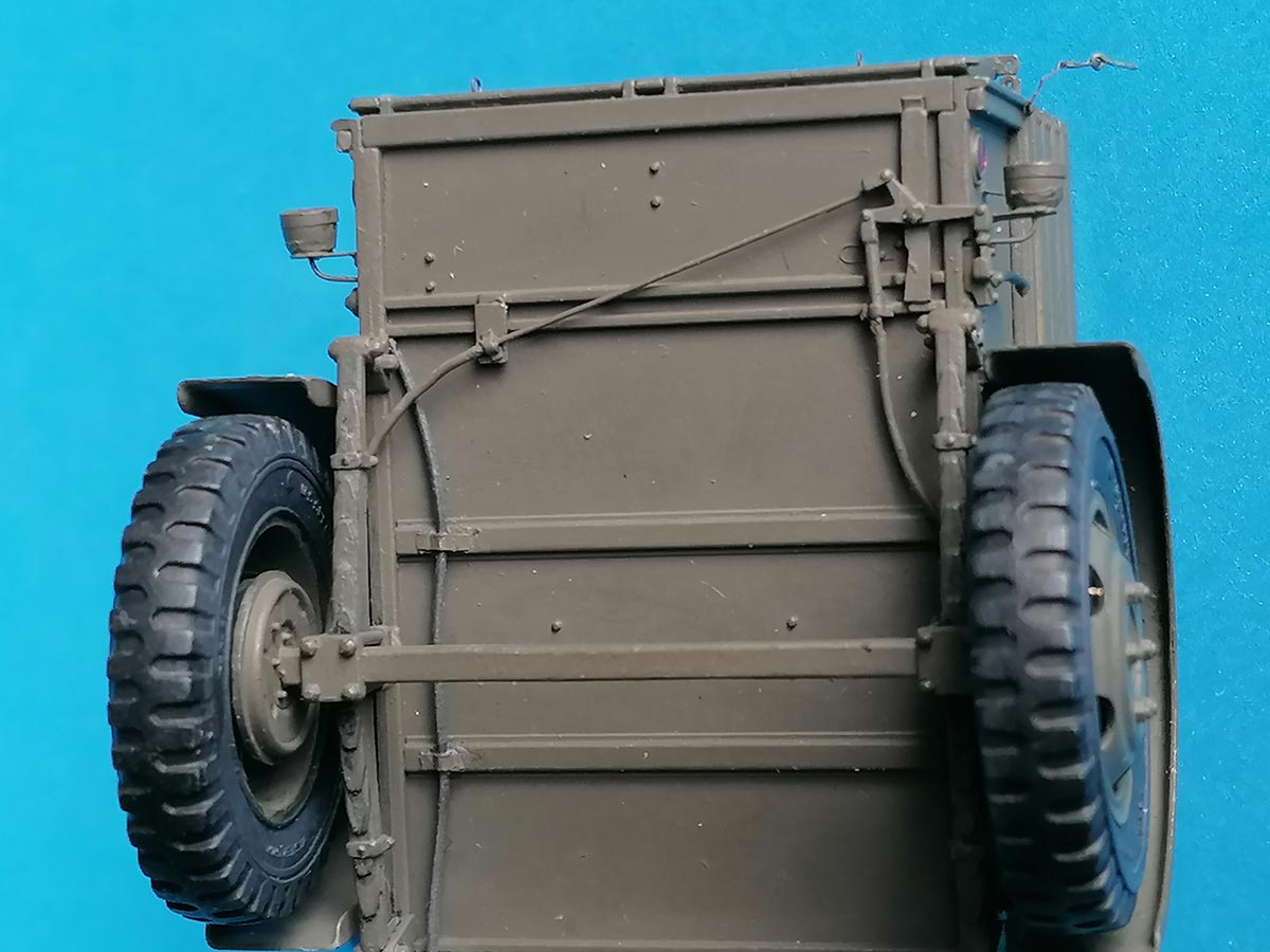
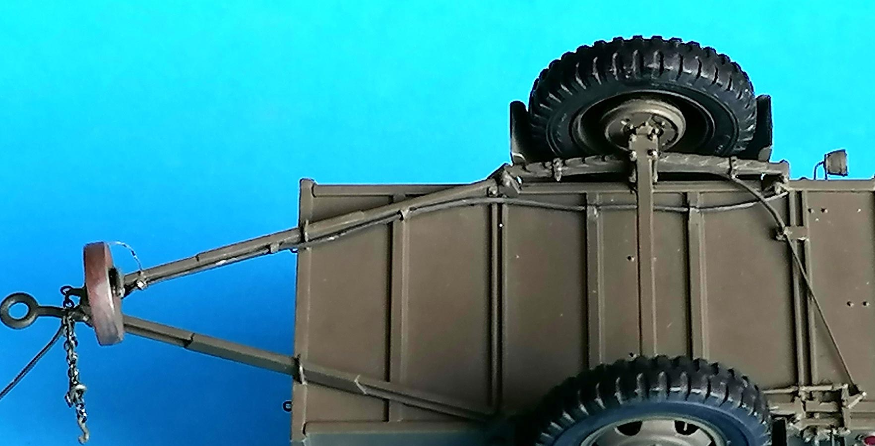 For the trailer light cable, I used a rubber filament instead of the recommended 0.4mm wire. The instructions don't tell how that is fastened on the prototype's draw bar and where it runs along under the load bed, so I fixed it on the draw bar with small styrene strips and then led it along the lateral frame and into it right in front of where the lead to te tail light comes out. the To give the plug Bk4 a little more weight, I drilled it out an inserted a piece of solder wire. )
| Painting / Weathering |
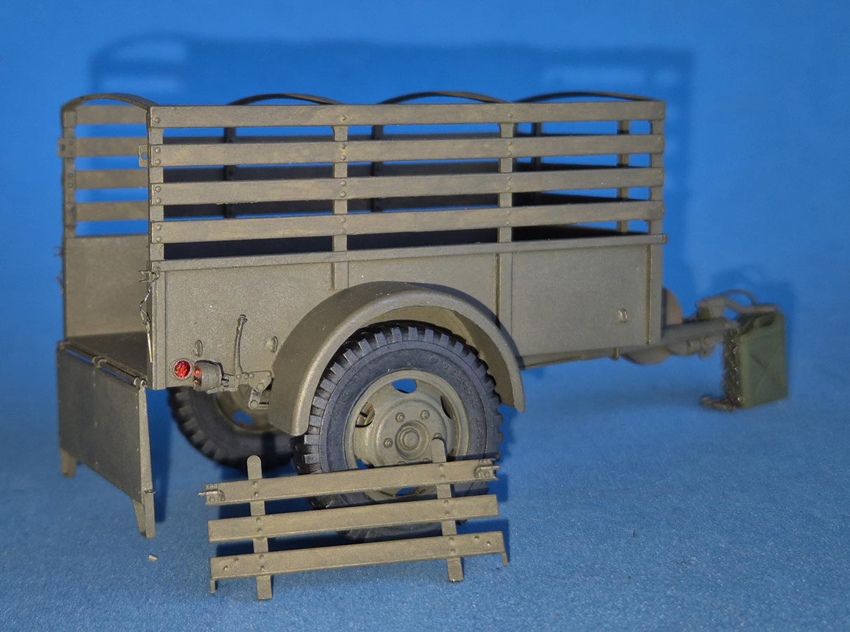 Painting was done by hand brush, with Humbrol enamel 55 gunmetal as primer, covered with Revell Aqua 46 Nato Olive lightened with a little matt white. The wooden parts were primed with Aqua 86 Olive Brown and overpainted with thinned Nato Olive. The reflectors received 2mm punch-outs from printed chocolate aluminum foil, affixed and covered with Future. The decals of the kit didn't appeal to me, so I just stuck a generic US star from my spares to the tailgate.
| Conclusion |
Over the years, I've built a number of models and regularly super detailed and otherwise refined them, so I'm really not afraid of small parts. But this kit surpassed whatever you would expect to get for a small model: 55 or so parts from plastic, 29 from PE, plus a piece of overscale metal chain come in the box, and you're expected to contribute four pieces of different thin wire. Some of the plastic parts are 1x2x1mm, the dozen brass tiedowns 1.5x0.6mm, and you're supposed to find and cut 21.8mm of 0.2mm diameter wire, to name just a few things. On the other hand, the wheels don't have valve stems and you're not told where the electric cable runs to.. – In short: A beautifully detailed little kit, but definitely nothing for beginners, while for advanced modelers a previous apprenticeship as a watchmaker would be advantageous. To each his own, but I for one will think twice before buying any more MiniArt kits whenever there are halfways decent alternatives from other manufacturers – I can create my own problems if I need any.
Bewertung:
| Price / Value: | ***** | Fitting: | ***** |
| Detailing: | ***** | Skill Level: | ***** |
 |
 |
 |
 |
 |
|
References:
© 03/2025 Peter Schweisthal
1668 readers of this report since 25.03.2025