|
|
 |
| The Original |
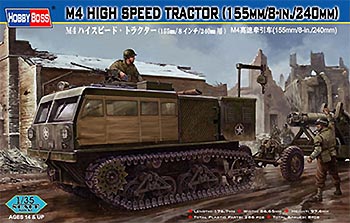
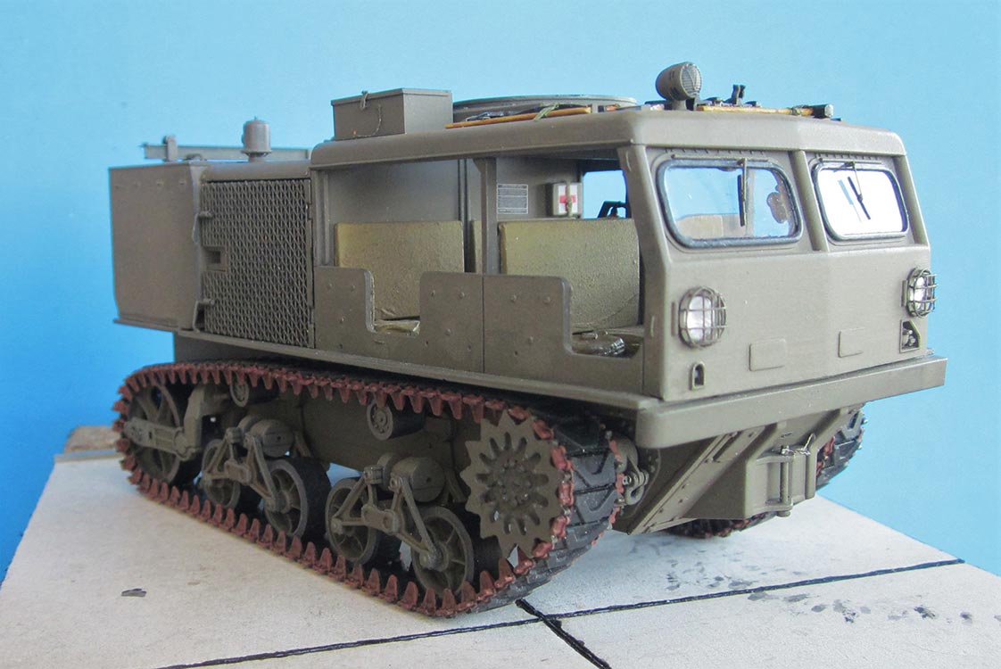
The M4 was produced in two variants that differed in the ammunition compartment at the rear which was conceived to either carry 3-in and 90mm "food" for AA guns or artillery ammunition of 155mm, 8-in and 240mm. It was also built in an "early" and a "late" version with fixed or hinged windshields, different return rollers and one large or three smaller openings in the hull rear.
| The kit |
I chose HB's kit 82408, as I wanted a front mover for my Long Tom. To get some informations, I also bought the books "US WW II HSTs" from both Tankograd and Ampersand. Internet references are listed at the end.
Eduard have "discontinued" their PE set for this kit (while the instructions can still be studied on the web, see below). So, I resorted to PART set P35-212, which left me with mixed feelings. First off, it's for HB kit 82407, the one for the AA ammunition, but it doesn't say so on the package. Hence, there were no details for my ammo box. And the instructions don't tell what to replace or what to remove from the kit parts, let alone how to bend what's in the set -- definitely not for beginners. On a positive note, however: My set came with a second main sheet of brass that wasn't perfectly etched and thus unsalable, but still had a large number of usable parts, e.g. all the stowage boxes. Wouldn't it be great if all PE manufacturers disposed of their mis-etched products like this!
| The build |
Vehicle
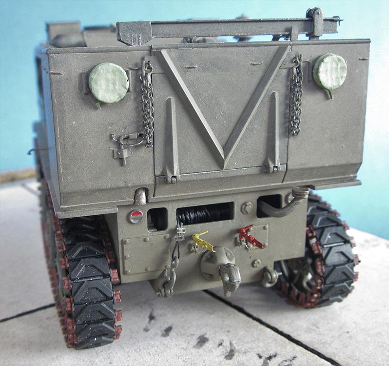
 The basic parts of the hull went together without problems, but the "frame" around the central winch outlet on the rear plate isn't on the outside on the prototype: instead, it belongs on the inside, if you insist on having it. As it was only after I had nearly finished the model before I noticed this detail, I restricted myself to the removal. If you want to display the winch compartment open, you might consider adding bodies to the taillights and the electrical outlet, but remember that these need cables, as well as compressed air tank C5 and gladhands A13 need tubes. -- On the front plate, parts F4/8 form
 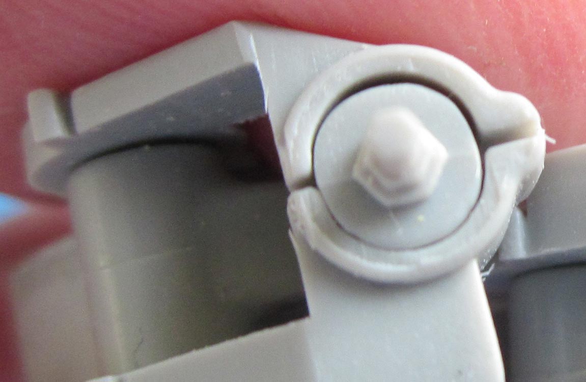 the front gun emplacement hitch and were modified for a separate hitch pin with securing pin plus chain. The central cab floor plate B33 was left unglued until much later to make correcting and installing the driver's controls easier.
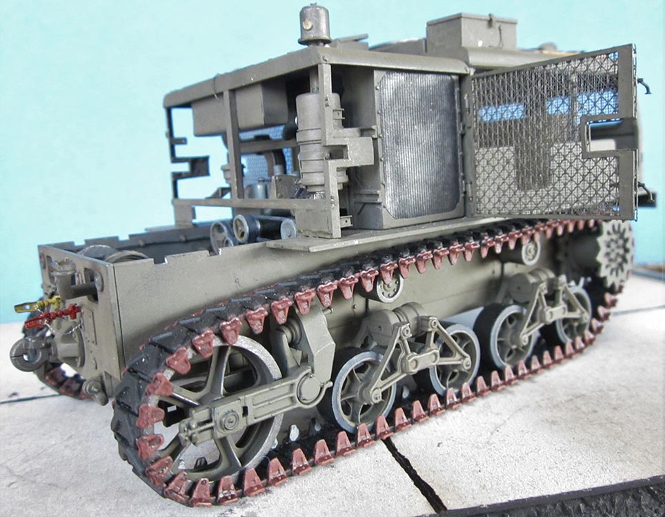
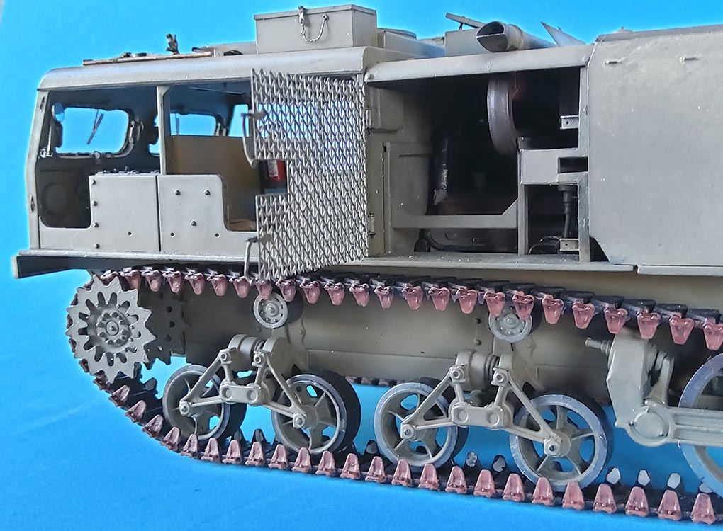
With the running gear, the idler wheel suspension halves leave an ugly open seam around the spring they enclose. To be able to fill and sand this as necessary, I cut off the hollow wheel axle halves and cemented them into the wheels. The suspension parts were then filled and sanded and received tiny wedges from 0.25 x 0.5 mm plastic strip for the "star" around the central nut. After drilling through the hole in the inside suspension half, a length of 1 mm rod could be inserted as a replacement axle (before mounting the whole thing to the hull!). 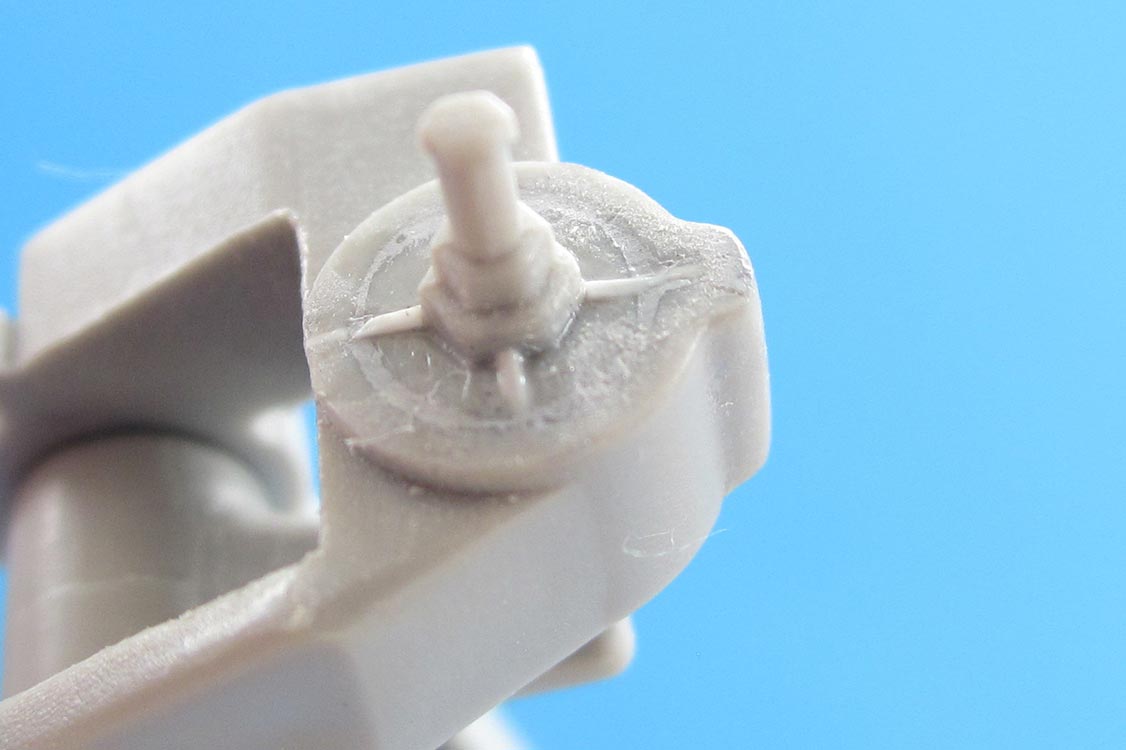
On the bogies, it should be noted that the volute springs' thinner ends point to the rear on both sides of the hull. Their end caps all received a 1 mm hole in their centers. The way the bogies mount to the hull isn't very strong, so it would have been better to install them after most of the construction handling was done. To make mounting the tracks easier, I cemented 15 mm of 1.5 mm Evergreen rod to 3.5 mm diameter disks of 1 mm styrene which could then be cemented into 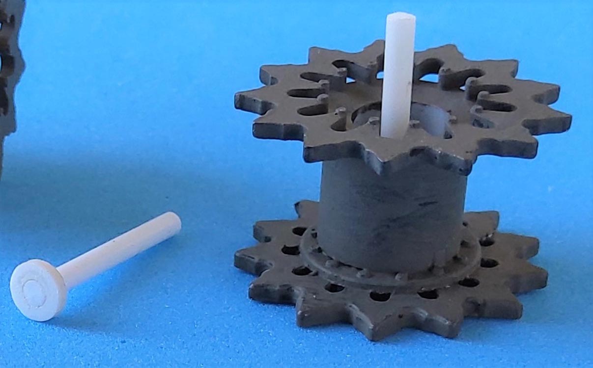 the inside halves of the drive sprockets. Holes of appropriate size were drilled into the sprocket mounts thru the hull, allowing the sprockets to be installed without glue.
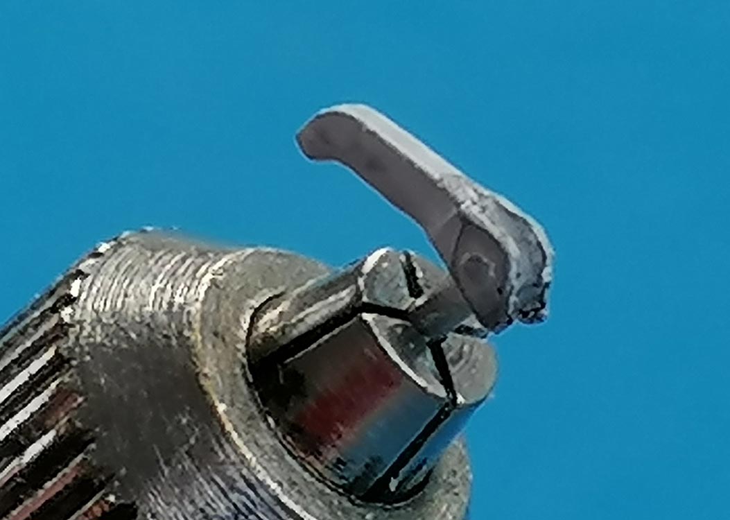
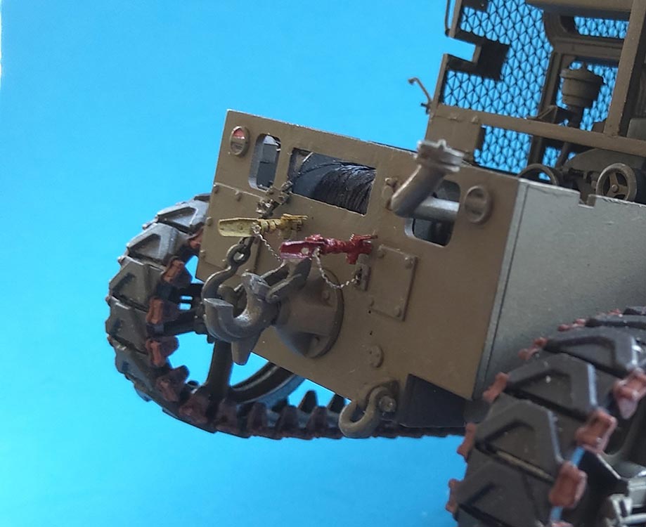 The pintle base C34 resembles the version for the AA ammo transport vehicle, so I cut off the protrusion on its right hand side. But what good is a tractor without a working pintle? I drilled through the hinge pin representation, then cut off the top quarter of the hook and reattached it movably with two Evergreeen strips. It only took a little whittling to make things look and work sufficiently. The gladhands A13 were detailed by adding T-shaped valves from 1 mm rod with tiny handles and "cover plates" from plastic strip with "securing chains" fastened on wire "crescents" for which the kit offers the mounting holes.
(The "chains" here are threads from brass mesh.)
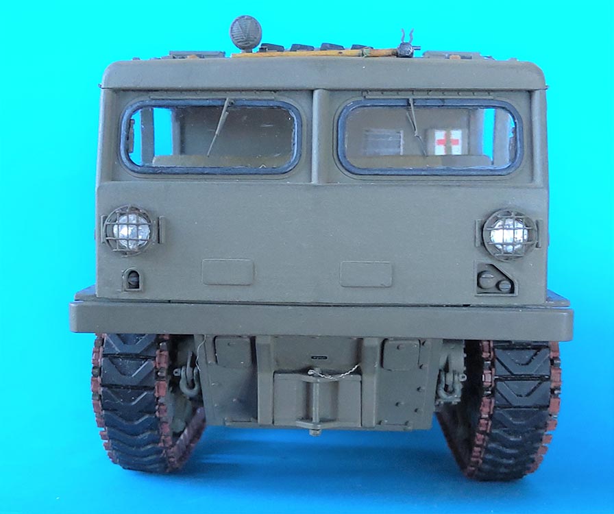
Having read in several reviews that the front bumper collided with the cab front, I test fitted and then cut down the bumper's mounting tabs before cementing it in place. Later, I found it necessary to close it on the inside with a strip of sheet to obtain a more correct-looking cab floor.
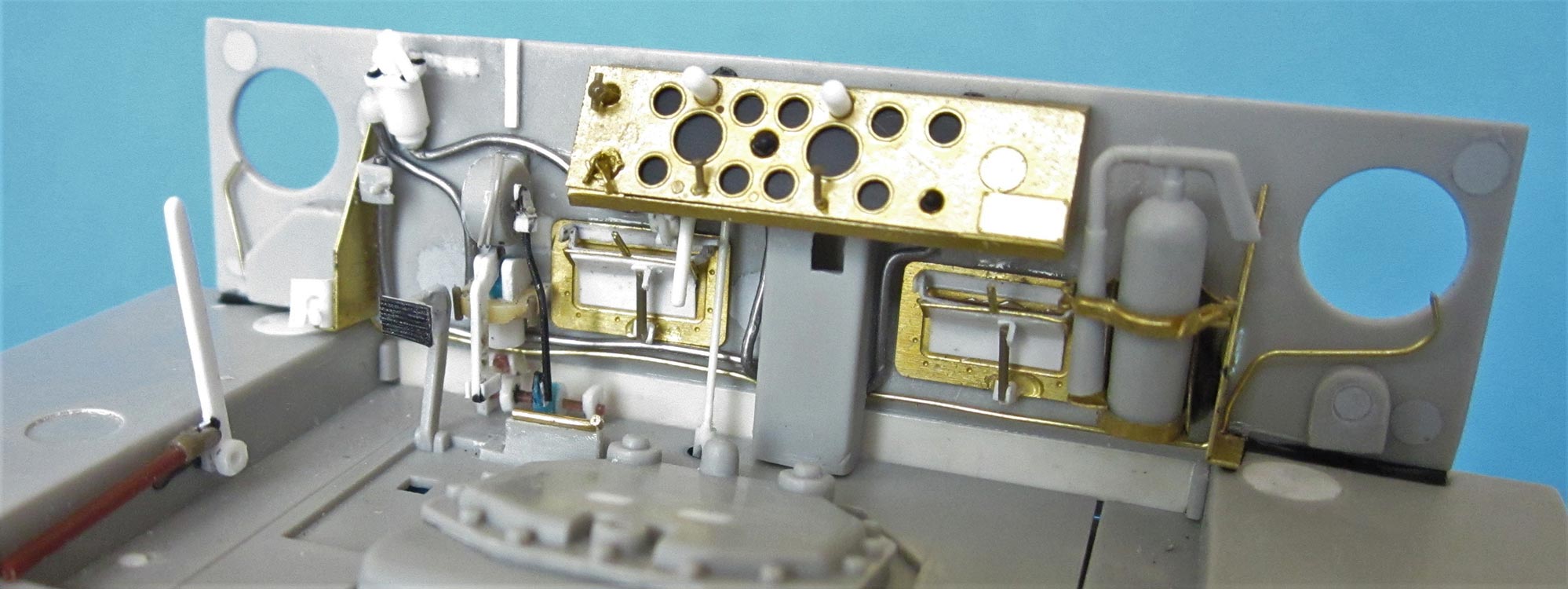
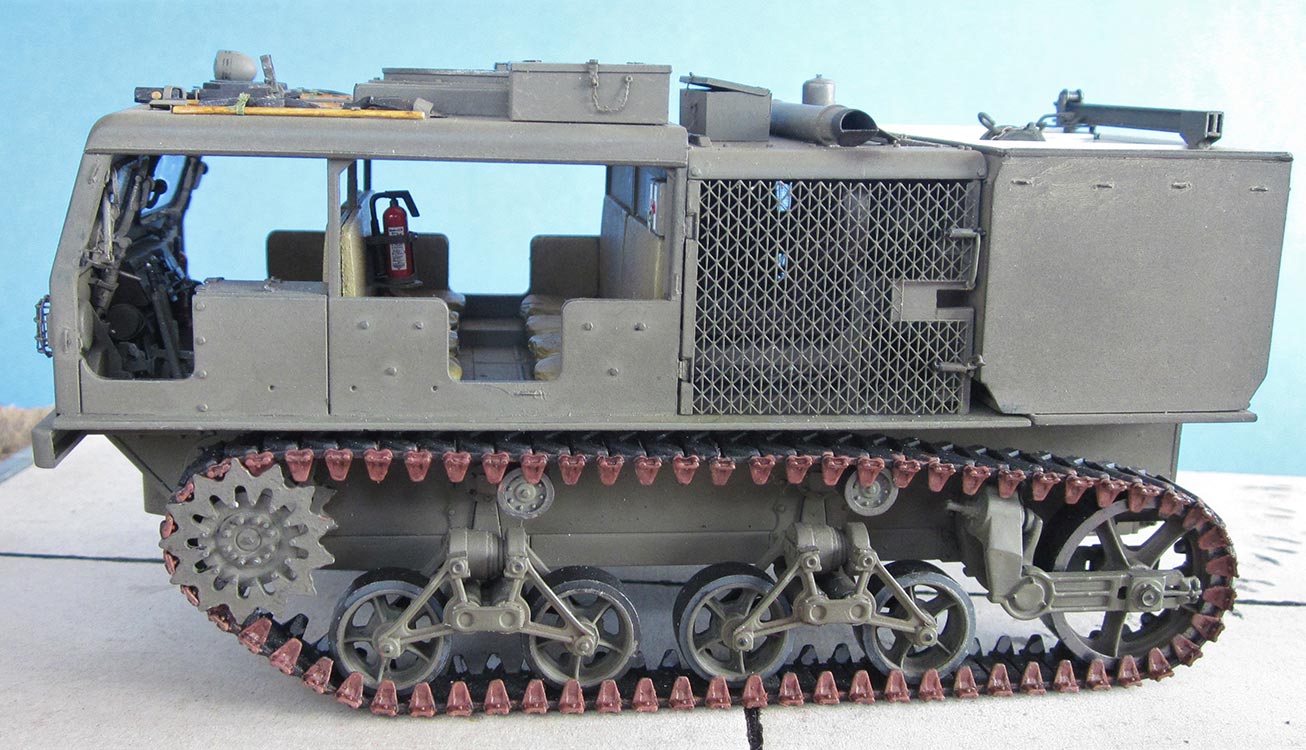
 Unfortunately, the cab front wall inside doesn't have the hollow recess between the panes, so the windshield arms can't really be installed correctly, and especially the distance between window opening and top of the lower recess is much too big: On the prototype, the tops of the side walls at the seats are at one level with the bend in the front wall, whereas in the kit, there's a difference of almost 2 mm there -- the sides should be higher and the front windows aren't high enough, as they should go down to the recess for the drive controls. I couldn't find a way to correct this.
 The clear windshield parts aren't quite correct in that they offer just the rubber seal and oversized piano hinges on the outside, while on the inside, they don't protrude beyond the cab surrounding. So, I added a 1 mm Evergreen strip around the opening to allow halfway correct mounting of wiper motors as well as scrap plastic and brass wire windshield lock mechanisms plus handles for pulling the panes closed. Eventually, I also removed the outside hinge representations and replaced them with pieces of 0.4 mm rod.
As for the windshield arms, HB offers two versions, of plastic (A20/21, ignored in the instructions) and PE. The problem being that in plastic you only get the pushed-out version, nicely different for right and left side of the panes, but without the circular arresting mechanism plates. These are present in PE, as are the arms in both open and closed versions -- but all these arms are for the right hand sides of the panes only! I cut apart the plastic parts and re-cemented them into the closed form, adding the PE circles plus short pieces of stretched sprue as locking grips. 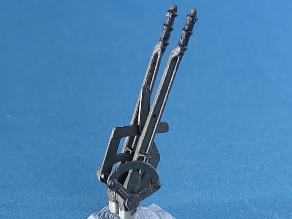
The steering levers had their molded-on ratchet operating rods replaced with stretched sprue plus guide plates. The PART ratchet quadrants unfortunately have the same innumerable tiny teeth as the plastic they replace, as opposed to the prototype's no more than twenty big ones. I don't remember if I accidentally cleaned off any "steering lever lock" representations on the grips' tops, but whittled replacement "wedges" from 1x1 mm plastic strip. Between the steering levers, there's the Power Take Off Lever, which seems to consist of a combination of two angled pieces of flat steel. I made that from plastic strip as best I could guess their positions and linkage. Clutch Pedal C23 received a thin styrene plate with several lengths of stretched sprue to give it some structure, as the PE part again had too many anemic ribs. To the left of the driver, there's the Winch Clutch Lever which was easily added together with the front part of its operating rod (which I made go beneath the driver's seat).
 In front of the PTO lever, there's a round object on the front wall and another contraption beneath it, with a perforated lever going down. The kit gives you these as parts C19/21, with the latter being ridiculously tiny. C19 was cemented a little higher and further left on the wall and received a lever plus an attached rod going down. Beneath it, C21's replacement was completely scratchbuilt and mounted with some guesswork linkage at its bottom. Above C19, a "Gearshift Lever Position Instruction Plate" from a piece of sheeet with two decals from Archer's "Generic US Data Placards" was added. The kit accelerator/trailer brake part PE10 needed a deeper cut between the two pedals, and the bending groove for its lateral footrest was on the wrong side of the brass. The mounting brace on the floor plate was shortened to the width of the pedal combo, thus also providing the room for C21's connecting rod whose function I don't know. Another foot rest at the bottom of the pedals was added from brass wire.
Two more things were added behind the left half of the dashboard: The Throttle Lever is mounted on a sort of a disk, with a few imitated nuts. To its right, another rod of unknown purpose with a "universal joint half" end goes into a hole that was drilled into the floor plate. Trailer Air Brake Hand Lever C26 was lost to tweezer launch and its scratchbuilt replacement relocated more to the left, while a scratchbuilt Siren Switch was added at the bottom of brass brace PE14. More to the right, C20 is a very poor rendition of the two "knobs on rods" below the dashboard that end in cables leading into the center column, so I scratchbuilt these "Engine stop and Choke Controls" from a little plastic sheet, 0.5 mm Evergreen rod, punched out disks, and stretched sprue from plastic and vinyl. I also scratched a rear view mirror -- stowed inside, think transport damages.
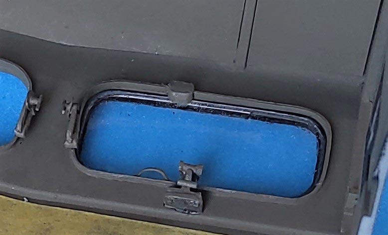
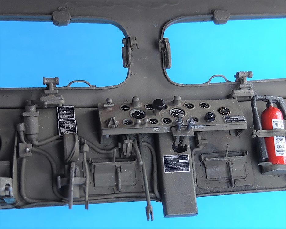 The PE set contributed two inside frames for the cab ventilation openings, but PART goofed with the rest of their mechanism, so I mounted what I had as best possible and added some pieces of sheet and stretched sprue to make it all look more plausible. Tiny C21 received a new home to the right of the central column and a wire connection. The PE dashboard was detailed with parts from the set, a few homemade ones, and different wires. Next to it, one of the PART fire extinguisher holders -- these two things are hopelessly over-engineered: five PE parts each, working! The platform for the second extinguisher (in the passenger compartment), however, had to be built after Eduard PE part 80 as seen in their instructions.
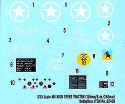
HB forgot to mention where their decals inside the vehicle should go: No. 10 obviously to the dash, and 11 to the wall of the .50 cal. ammo box to the driver's left, right next to his elbow. No. 12 belongs to the dash's central column, below the hole for the "knobs on rods" C20. For the PE dash, I used PART's piece of film, and additional decals came from the Archer set for the HST, their "US Generic Data", and my spares.
The three seat "benches" were replaced with parts cast off a fellow modeler's Masters Productions update set.
All back rests and lateral pads were covered with a single layer of paper handkerchief, affixed with dabbed-on thin liquid glue. As the molded-on rests on the back of the wall behind the driver were conspicuously thinner than the separate ones for all other seats, I cemented pieces of styrene sheet on top of them. All "cloth" was painted Revell Aqua Color Olive Brown, the seat belts Earth Brown. The First Aid box received a decal from my spares and an onionskin paper strap with a wire buckle.
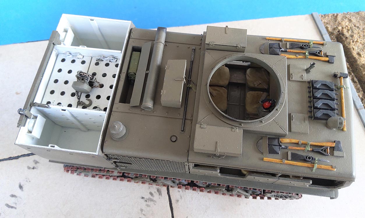
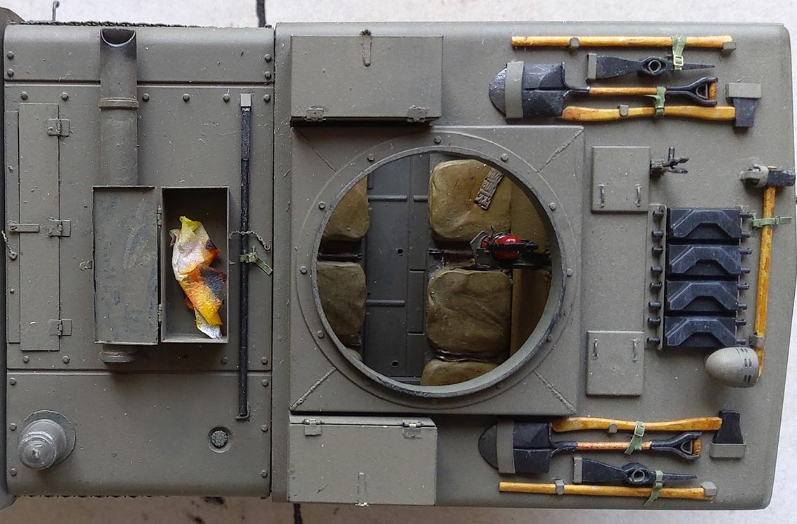 With all positioning holes on the roof going through, I felt it necessary to cover the inside with pieces of thin sheet. (The positioning holes for the stowage boxes should be filled, as the boxes should end in line with the rear of the MG inset.) All tools had their stowing brackets and such sanded off and replaced by the respective PE parts. Many of these were wrong (or at least to be placed the wrong way round -- just like the corresponding Eduard parts, BTW): Not every single tool has its own tiedown strap, as for most of them, there are just tiedowns with a strap that goes to a tool on either side, pulling the two into their respective sheet metal angles. The pickaxe heads share that strap and tiedown loop with their handles; besides, they are fixed by the bracket at their wider end and a piece of tube coming up through the opening for the handle -- that hole, by the way, seems to be terribly difficult to mold, as I have yet to come across a kit's pickaxe head featuring it. As for the MG tripod, the PE parts for its stowage didn't make sense to me, so I decided to leave them and the tripod off and just installed four tiedowns from stretched sprue. I made my straps from onionskin paper painted with water colors plus PE buckles.
On the prototype, the front spare track holder has slots -- PART gives both with holes, so no chance to insert spare track links before opening one row of holes. The roof inset with the MG ring lacked the weld lines into its four corners, so I added them from stretched sprue. Parts B17,18 for the MG mount were so huge and so little detailed that I decided to leave them off. But there seems to have been a barrel clamp welded to the roof, and neither HB nor PART had anything for it. I whittled the clamp proper from 1 mm sheet and made the circle that I saw in photos with my punch and die. The mount to the roof is guesswork, but I'm prepared to correct it as soon as someone shows me what it really should look like.
PART gives three replacement stowage boxes with movable lids, as it does for the locker behind the exhaust. Bending the boxes and their separate lids was easy; finding out how the working hinges have to be bent (upwards around thin wire, so their mounting rectangles can be fastened on the lid), however, took me some serious thinking. The box latches can be installed movably, too -- once you find out where to cut between the two parts that look etched as one on the fret. The stowage box behind the MG opening, B46, is to be mounted the wrong way round in the kit: it has to open to the front, 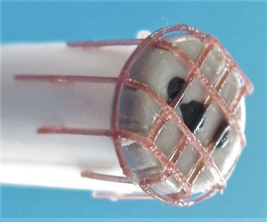 to be accessible from the manhole; this mistake is repeated in the instructions of both PART and Eduard.
There's a faint mold line running all around the roof and down the A-columns that I sanded off. Instead, a separation line was inscribed between roof and the walls and columns below it, and lengths of 0.4 x 0.5 mm strip were cemented above the doors as rain gutter imitations. All around the model, the tiedown representations were removed and replaced with ones from stretched sprue, plus some missing ones.
Part C54 doesn't appear in the instructions, but turned out to be a very welcomed bending aid for the headlight guards: While it wasn't needed for bending the kit's PE, I cemented it to a piece of sprue and coated it with several layers of Future so that stretched sprue replacements could be formed and joined over it, with outer rings added that are missing from the kit's (and PART's) 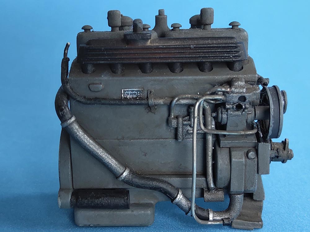 brass offerings. Lamp reflectors were made from thinnest aluminum foil formed over the round end of a drill bit and installed with Future, as were the kit's clear lenses.
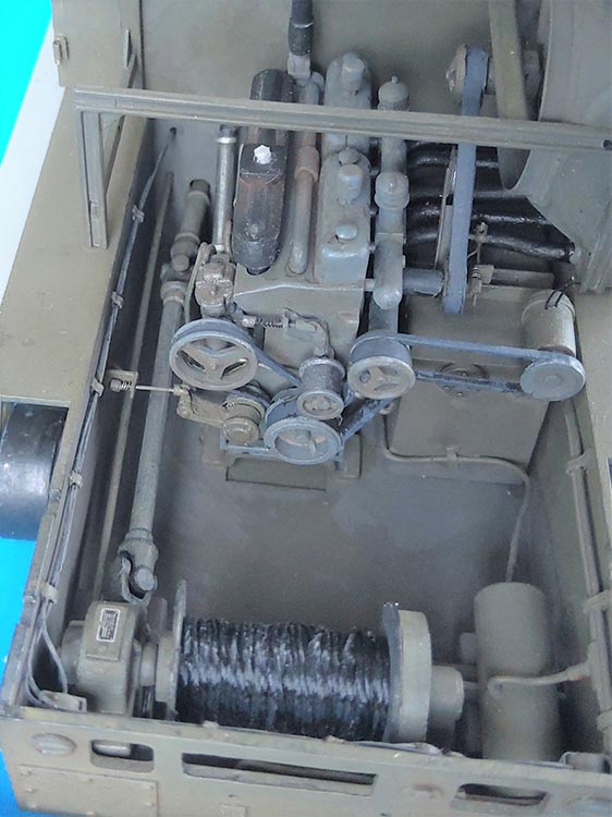
The engine block needed a fair amount of puttying before I installed its many add-ons. Once I had found the engine's TM, I felt obliged to add some tubes that can be seen on the left side. The instructions don't tell you that B19 belongs on the pin of B12, and C32 onto the fuel tank (C64/B30) so it can connect to the other end of belt B9. I added "flanges" to most all pulleys involved. All belts are of a non-scale thickness, but I ignored that. B12 and B49 are "belt tightener pulleys", and as such have to be adjustable. B19 does that for B12, with its supplemented axle mounted to a piece of angle on the engine. The adjusting rod ends in an angle on the left hull wall. If you want to detail B49 correctly, some more scratch building is required. 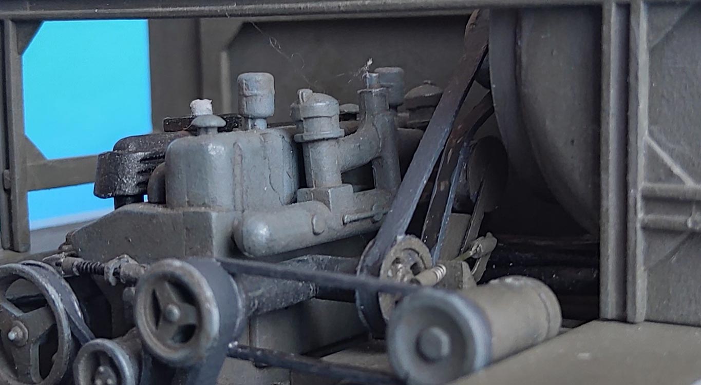
As for fan drive belt B40, it needs a tightener pulley on the fuel tank that's not contained in the kit either. Adding this and its arm (that mounts in the molded-on "channel") also meant replacing the lower run of the belt with a piece of 0.5 x 1.5 styrene strip that could be given the necessary "kink". Again, an angular brace with an adjustment rod was required. Part B7 represents the "Fan Drive Assembly", but badly so: it is too thin and has a round bend, which would make it impossible for it to house bevel gear wheels. The replacement piece from 2.5 mm tubing required changing the mounting point on the engine. 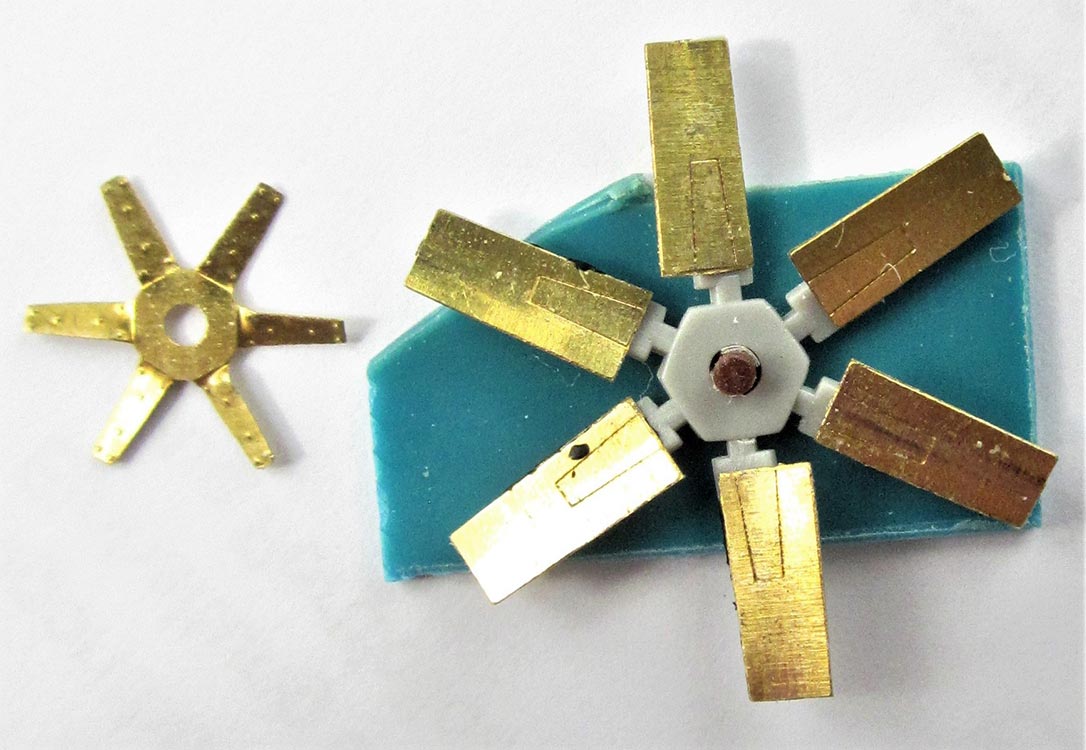
The PART set offers the engine fan center and markings on the separate blades, but if you fix the "star" into these, the fan will become too small in diameter. To solve this problem, I made a jig from a piece of 1 mm plastic sheet with an axle from styrene rod upon which I placed the narrow-bladed kit fan. The PE blades were curved slightly and then white-glued to their kit counterparts, which took care of the right diameter and identical angles. The center part could then be bent correspondingly and superglued to the blades. The fan housing ring is of thin sheet metal on the prototype, so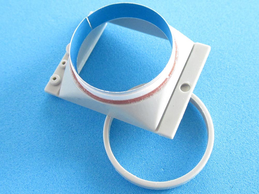 I couldn't live with its thick representation in the kit and sawed that off. A strip of sheet aluminum was temporarily placed into the opening as a former and around it, thin plastic sheet was cemented to the fan housing and "welded on" with stretched sprue. Inside, I cemented a sheet rectangle that had been adorned with a piece of fine wire mesh, painted matt black and then drybrushed aluminum. The fan mounting tab on part B38 was too thin and had to be replaced.
 At the bottom of the fan housing, there are five "nubs" that represent fittings for the coolant hoses. I drilled holes into these and inserted insulated wires for the outer four which I then led into the abyss between tank and engine. The thicker central hose (for the engine cooling water) was made from solder wire that I connected to part B29. Actually, all that "hosery" isn't really visible -- but I know it's there… Instead of the knob on B39, I took a slice of 1.5mm plastic rod, notched its rim and cemented it to a short piece of 1mm rod to come up through the hole in the roof.
 In a TM illustration shown in the Tankograd book, the box under the engine roof (C37) is called water can stowage. As the PART set provides a movable lid for this locker, I cut the roof open and added a new box from sheet styrene, large enough to now hold two cans from my spares. This box later collided with air hose B21, so I replaced that with a piece of solder wire that could be bent as necessary. The external muffler shroud is of thin sheet metal, so the plastic needed thinning down around its outlet. Four hex-head bolt heads were glued to the outside of the engine roof corners.
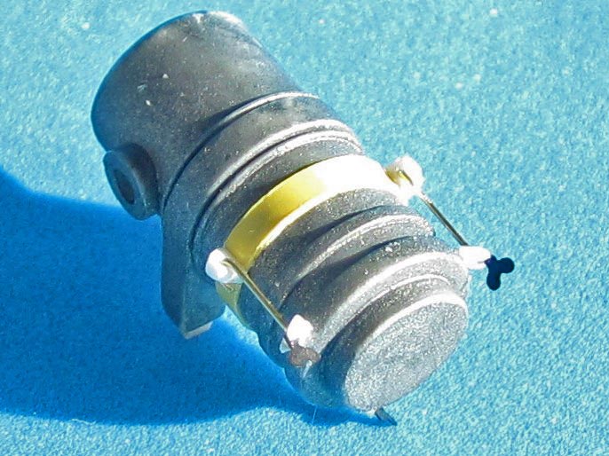
I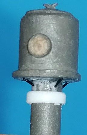 n one of the Primeportal pictures, I discovered that the circular protrusion on the side of air pre-cleaner B6 is a framed piece of glass, so I drilled it out a little and put in a punched-out sliver of acetate. Four support struts from stretched sprue were cemented underneath. A circular perforated piece of thin styrene was added as a "seal" around the pre-cleaner's stem. I added another strap around the air cleaner C40/44, to which three small plastic triangles were glued into which brass wire was hooked that leads down to plastic clamps with ABER wing nuts.
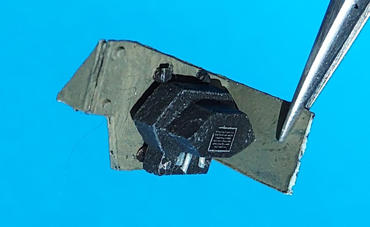 To the left of the cleaner's bottom, there is a black contraption that is bolted to a metal plate which in its turn is supported by the rear roof supporting frame and the fan housing; that's the Voltage Regulator, connected by wires to the generator below it on the fuel tank, part C32 (as mentioned above). To mount that scratchbuilt part, the lateral roof supports had to be joined. Research showed that the kit's representation of the supports (C43,47) was incorrect in not showing the braces at their bottoms, so I turned to the PE set. That offered better, but extremely fiddly replacements from tiny parts. Not being the Great Solderer in the first place, I didn't try my luck here but just used instant glue and then filled some hollows with Green Stuff for stability. The result was completed with a length of Evergreen 1.5 mm angle that also allowed the lateral extension of part C4 (another filter?) to find a support. From the center of the cross brace, a piece of 1.5 mm Evergreen channel goes up to the roof.
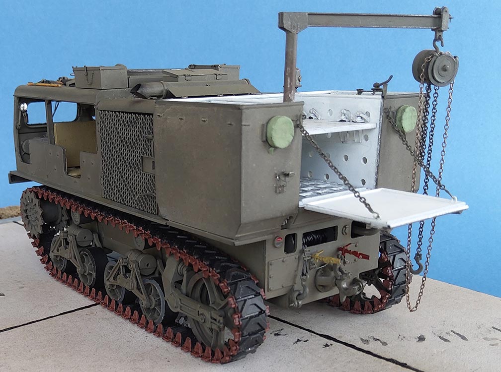
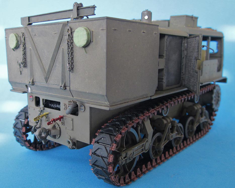
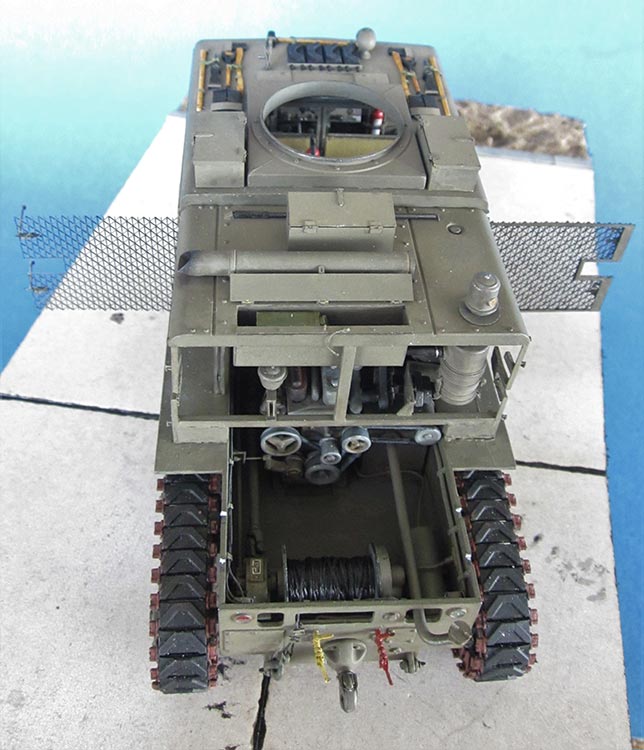
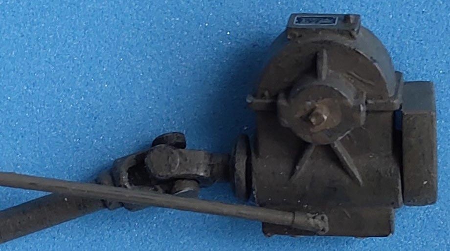 With all the work done on and around the engine, I decided to leave the ammo box removable to show off what I'd done. I shied away from installing all the inner hull braces, but there was a sufficient lot of work to do without that: The winch drum received a strip of 2mm width on its right and was wrapped with strong black low-fuzz linen thread instead of the kit-supplied white nylon hawser. Next, I wondered where that rod from the Winch Clutch Lever would end up: at Primeportal, it (predictably) appeared next to the winch drive shaft, but it took me a long search in the web to discover roughly where it goes on the winch. That search also showed that the winch housing needed some small additions like a type plate on a rectangular mount on top and an automatic brake representation facing the rear hull wall. Some more small items like taillight and trailer lighting receptacle bodies made the winch compartment look busier. They all received "cables" from stretched black vinyl sprue, and "compressed air lines" from thin solder wire were added between the air tank, the engine and the mounting holes of the gladhands on the outside. -- All of the engine and its compartment were treated to Vallejo's "Engine Grime".
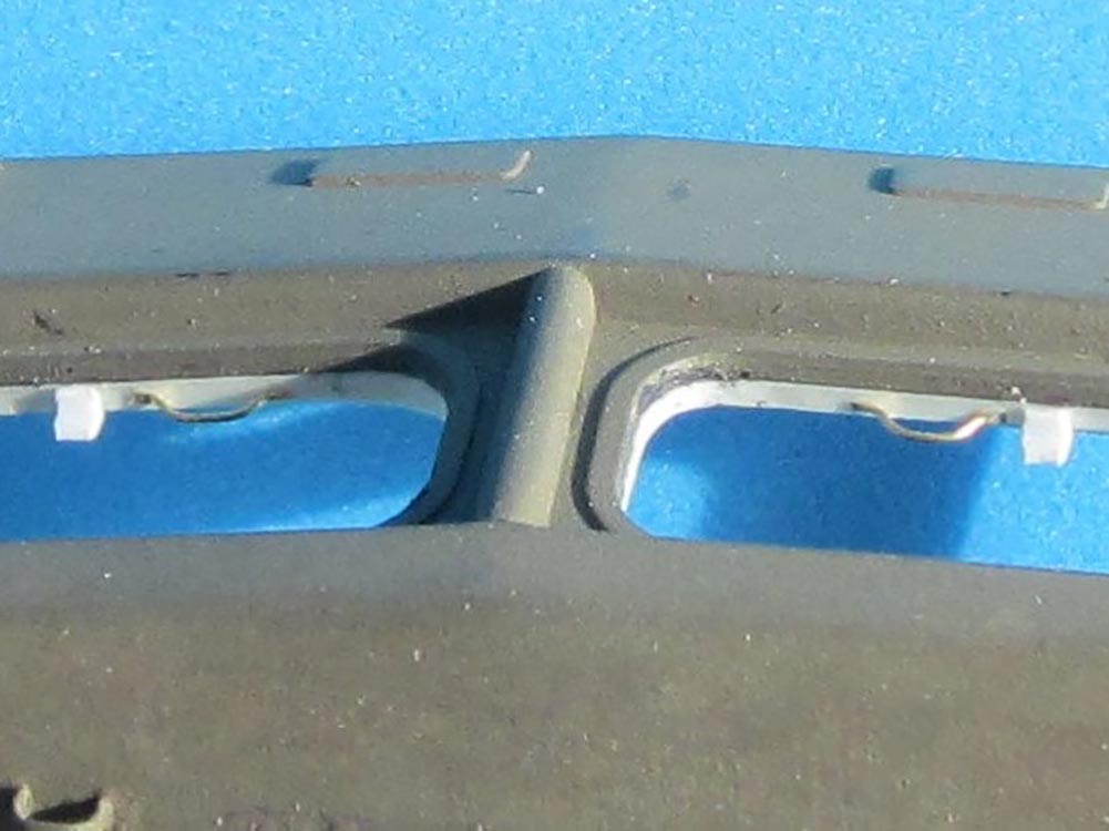
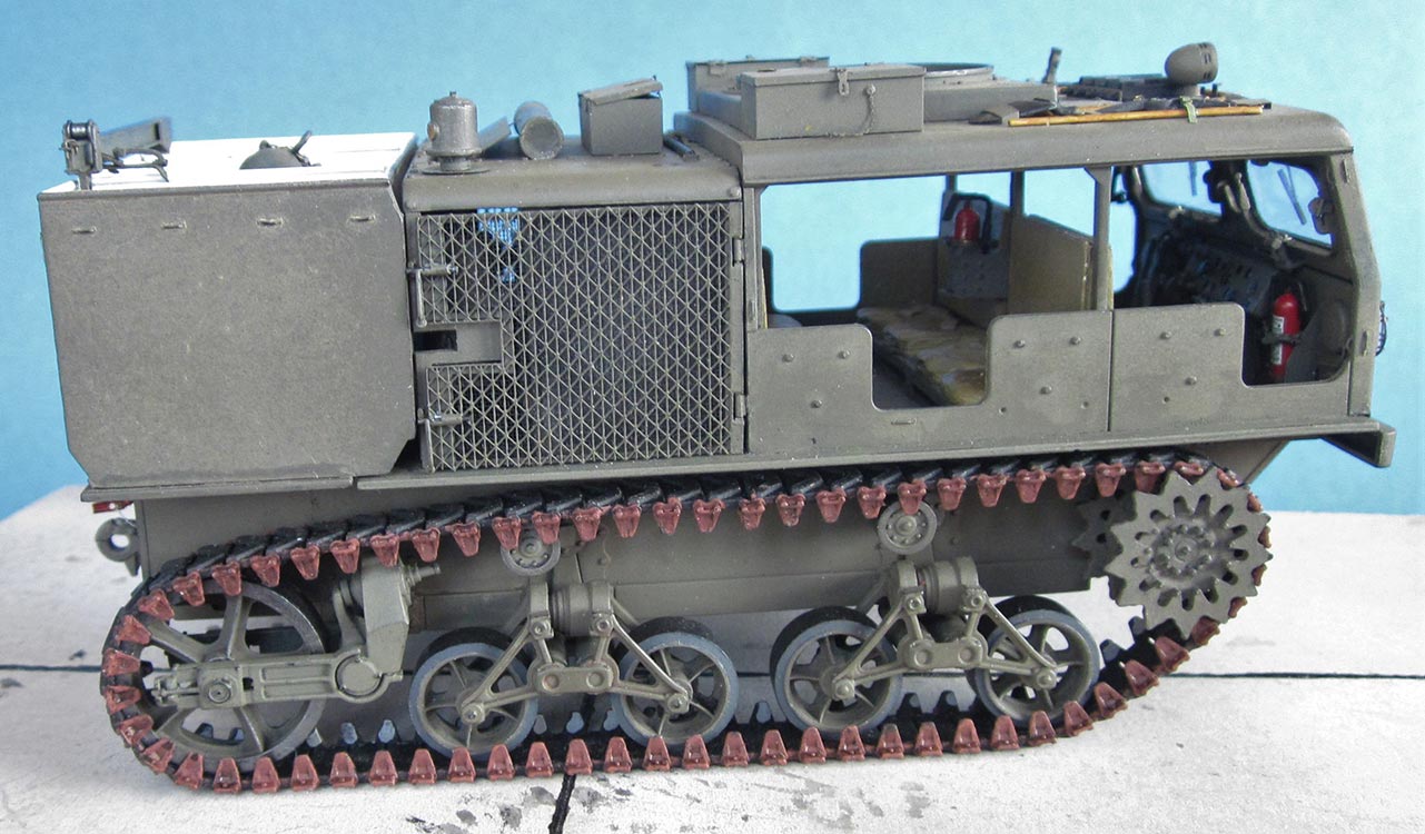
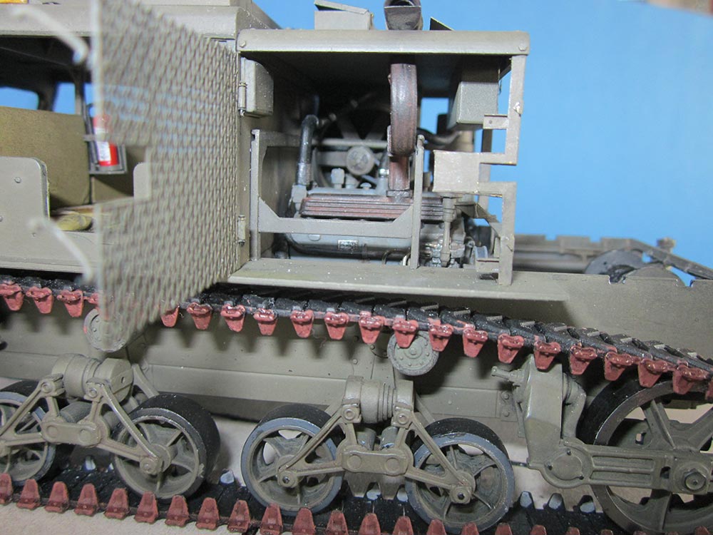
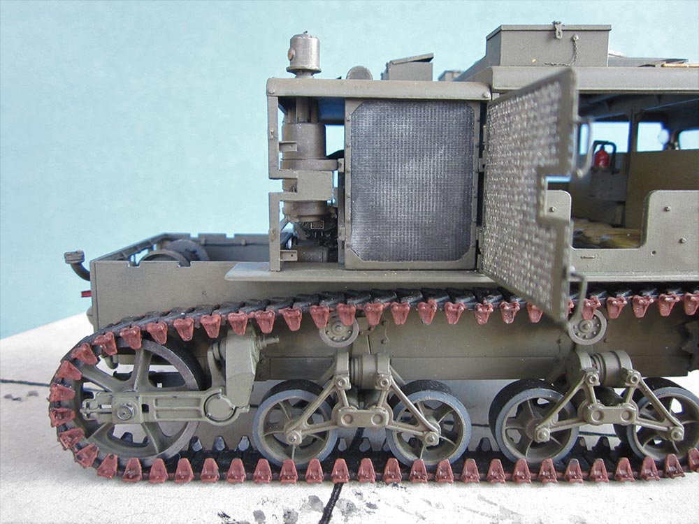
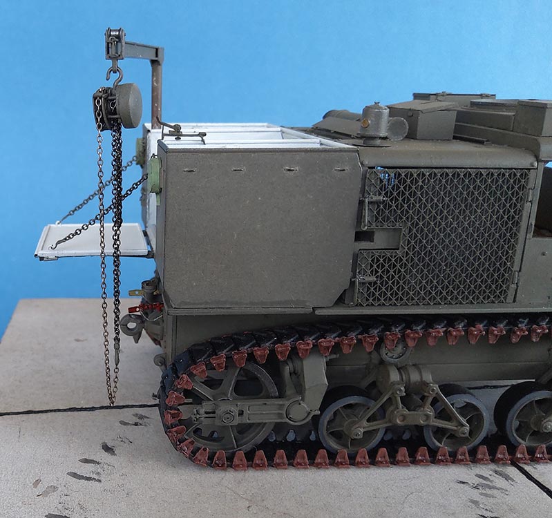
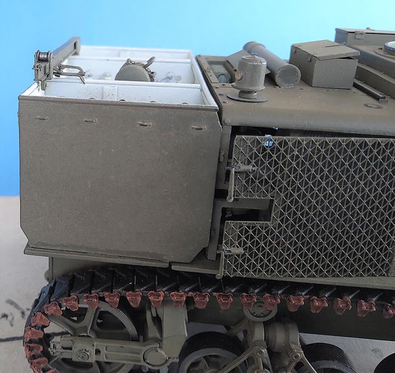
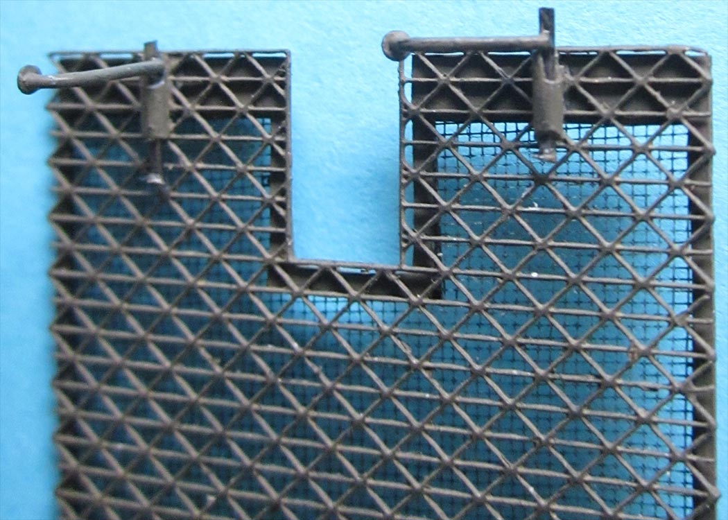
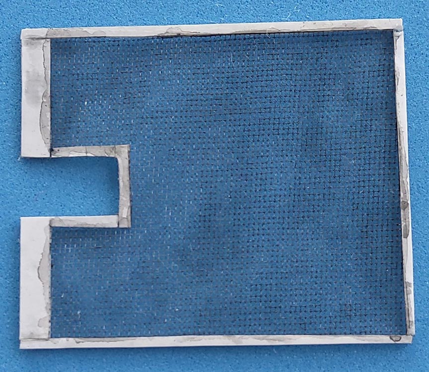 Before closing in the engine bay, research once again paid off in additional work: On the prototype, the radiator is protected against leaves and other obstructing flying material by a sort of screen door that sits between it and the grill; it is mounted to the grill and opens with it. I don't remember where I'd found that nylon netting with half-millimetre mesh that I framed with strips of Tamiya "Pla Paper". PART gave me a second set of grills, so I had to choose. The kit's PE is to be glued in place, whereas the AM parts have working hinges. Besides, their latticework is not only finer but also more correct in that it doesn't have connecting lines at top and bottom, so I chose PART.
Unfortunately, while the kit supplied roof supports have faint representations of the later version grill locks, PART offers nothing in this respect, the reason being that their grills have tiny holes for the early style locks that they supply (after all, their set is for the other HB kit that builds into an early type vehicle). As my kit is of the late version, I had to cobble up four "gates" from plastic rod and sheet as well as handles from 0.5mm plastic rod sliding in 1 mm stretched tubing. Crazy, but that's my idea of modeling fun, as opposed to painting the results. However, it turned out that the lateral cutout of these grills is a fraction of a millimetre too tight for their roof supports' protrusions, so my grills can't fully close, let alone be locked. The problem was made worse because the cab rear wall doesn't stand really perpendicularly, but leans slightly backwards; that meant that the lower hinges had to be beefed up to mount the grills. Which resulted in countless trials and errors of white gluing hinges that had received yet another layer of thinnest styrene -- in short, fixing these things cost me at least a week of modeling time.
Ammunition Box
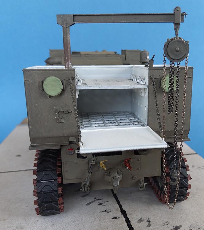
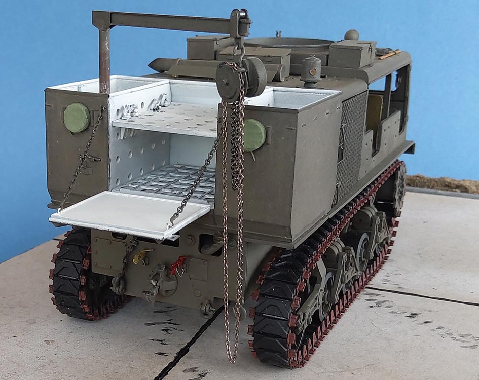
The kit's Ammo Load Box had an outside ridge near the bottom of its front wall. I couldn't find photographic evidence for this, so I removed it. Lacking the Eduard PE set, I had to make the vertical "channels" on the walls of the lateral compartments from Evergreen 3.2 mm H-beam that I cut down into a "C" profile. I'm not sure that I cemented them in the absolutely right positions, as I couldn't find definite photographic evidence and feel that following Eduard's instructions may have brought them too far back. The positioning aides on the outer walls were ground down to resemble weld beads. Another drawback of the kit are the missing inside vent representations on the side walls. Eduard offered parts to replace the vents, but without them, I sanded off what was molded to the outside. After all, there were many "late" tractors with vent-less "early" ammo boxes. The rear pair of floodlights had "cloth" covers from onionskin paper added.
While I was in the area, I drilled out the ends of the "tubes" on top of the box walls. Only to discover later that these tubes aren't overlapping at the box's four outer corners, but mitered, so I made new tubes from 1mm Evergreen rod whose ends I only drilled out on the hatch and next to it. Before these new "tubes" could be mounted, however, the box had to be cemented together, and there appeared the next inaccuracy: Just like the tubes on their tops, the walls didn't overlap on the prototype, but were welded at the corners, and the strip at the bottom of the rear wall went right to these corners. So the seams between the four walls had to disappear and that strip extended across the side walls' thickness.
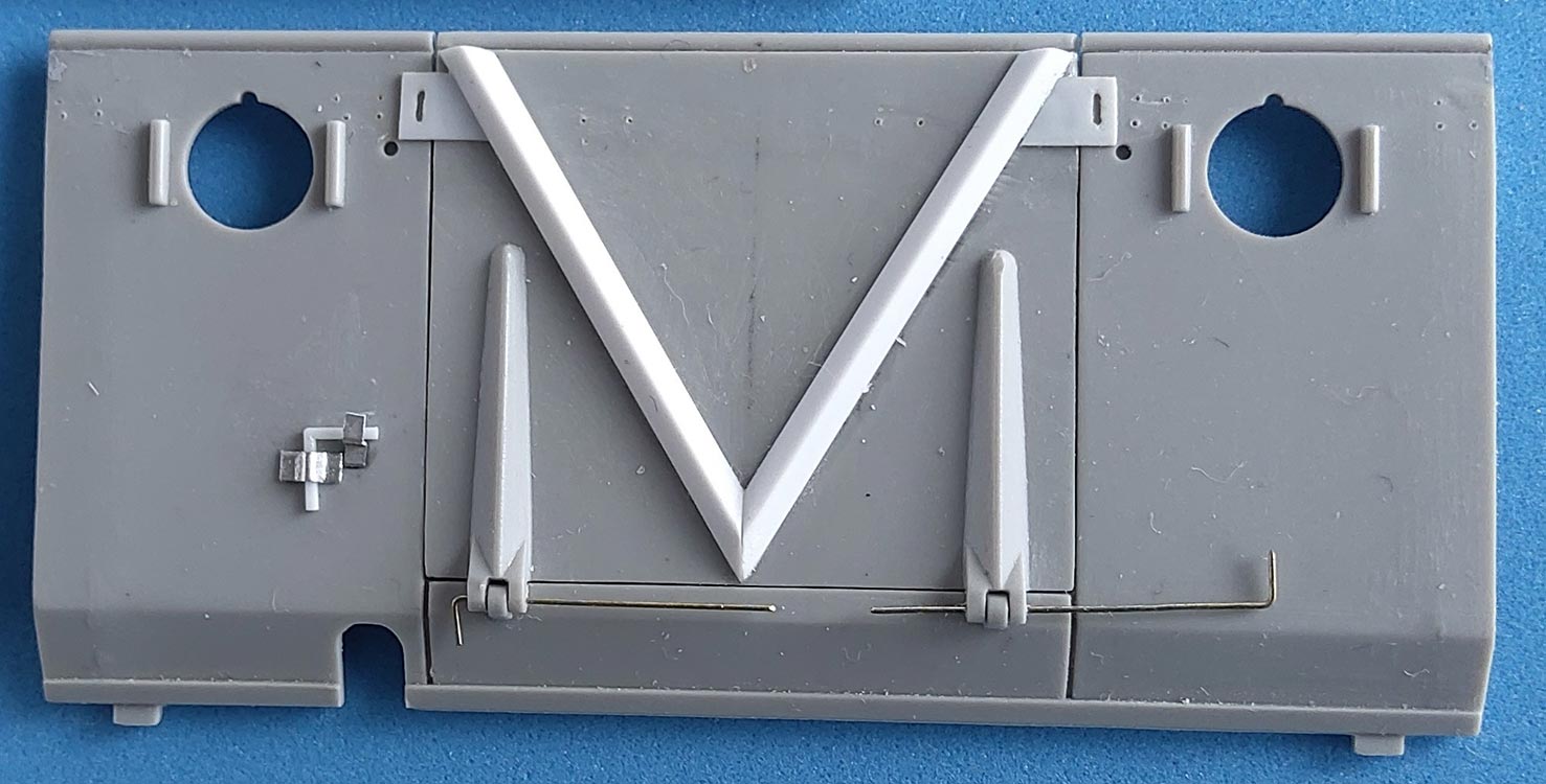 The hinges of the hatch were drilled through to make it movable. And then I noticed that the stiffening "V" was wrong in that it was neither beginning at the hatch bottom nor reaching its top. Correcting this could only be done by completely removing and replacing the V with Evergreen 1.5 mm L-angle, as the upper ends of the molding already touched the hatch sides. New securing chain "ears" were added on the hatch and the chain eyes replaced on the box, as were the tiedown loops that were wrongly molded too high on hatch and rear wall (and were missing on the front wall). The hatch also received a frame from 0.5 x 0.5mm strip and two eyes for the chain on the inside. With the kit chain being of the flattened kind, it, too, had to be replaced, with hooks bent from wire.
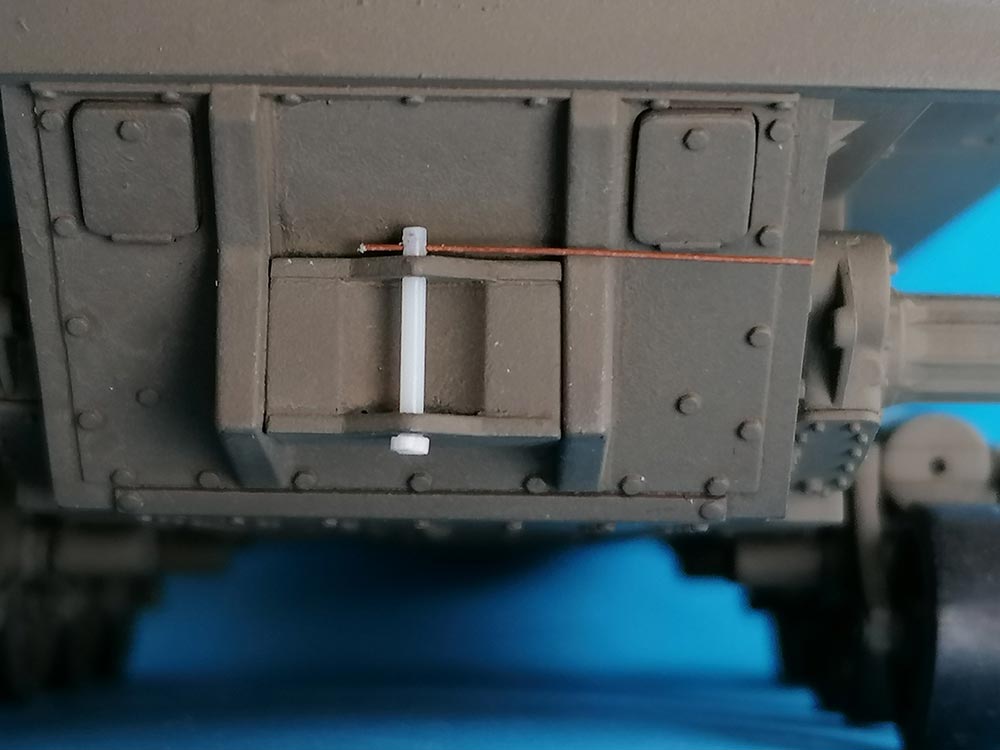
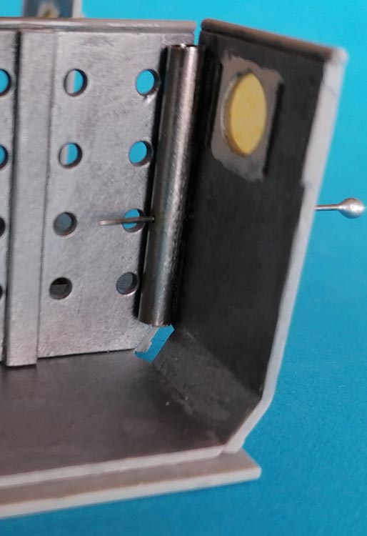
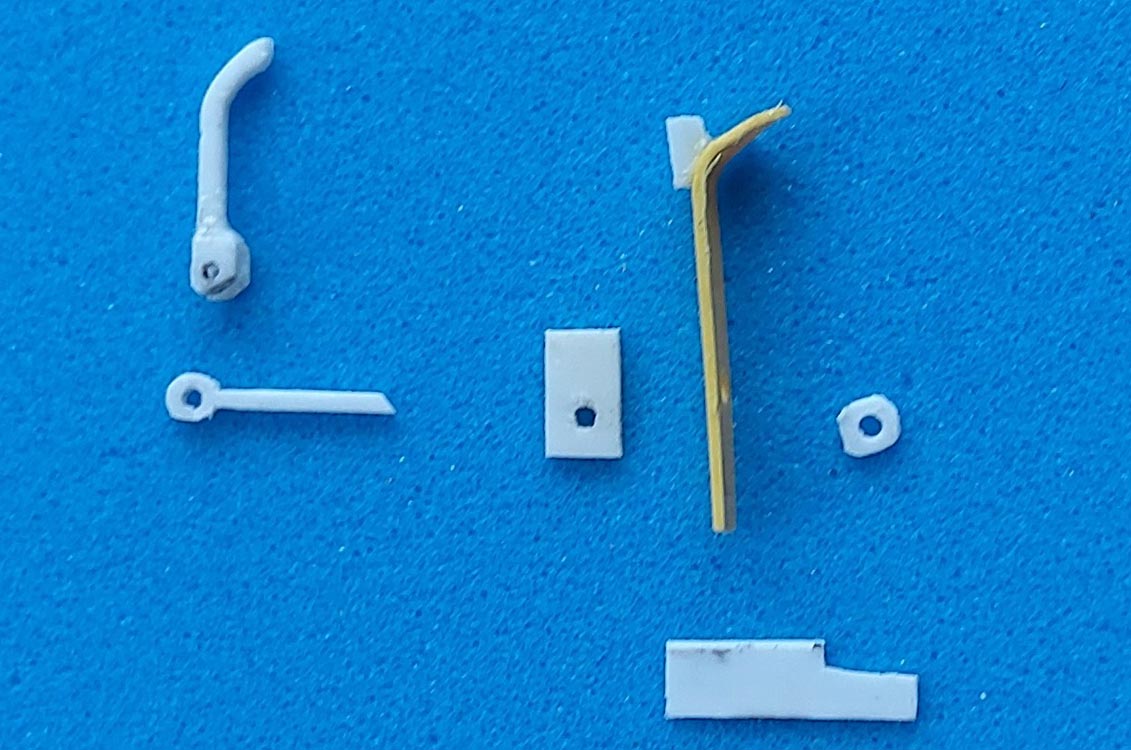 The ammo crane's boom had several deep pushout marks, so it was replaced with the Evergreen H-beam I had used for the "channels". At its working end, the upper left corner was drilled through and a piece of thin sheet with a hole cemented under the right corner to hold a 0.3 mm wire angular "U" as "Roller Stop Pin". The stowed crane boom is kept from swinging around by its lock on the right hand side of the hatch. A 2 mm wide plastic strip was cemented vertically right beside the hatch, and about 1 mm above the wall a horizontal strip was added that had its other end bent to rest on top of the perforated partition. A "needle" with square cross-section goes through a round hole in this strip and through a square hole in a securing plate, to be cemented in a counter plate. By means of the handle, the securing plate can be rotated over the boom's lower flange and fixed there. The handle is secured against unintentional loosening by its end resting in a piece of half-pipe.
 The "Lock Pin" and its stowage points to the left of the hatch were replaced, too, and a hole drilled right next to the end of the stowed horizontal part of the pin. The pin would go through the guide pipe on the inside to support the crane pillar in its "up" position, while its "chained" end would be rotated behind the stowage clamp. The pipe does not stick out of the box's bottom: what can be seen there is the lower end of the crane's pillar when in traveling position. Which shows that the kit's pillar is way too thin, so I replaced it with 2.5 mm rod (which at the same time took care of the fact that the 1:1 pillar's diameter is slightly larger than the boom's width, hence the weld beads there). The pillar's length equals the height of the box, as the stowed pillar ends at the bottom, while the boom rests near box top level. To show the crane working, I then had to drill through a guide tube of suitable diameter and found it in the form of a 3 mm metal tube -- no idea where that originally came from. The pin's securing chain is latex filament from the top of black pantyhose.
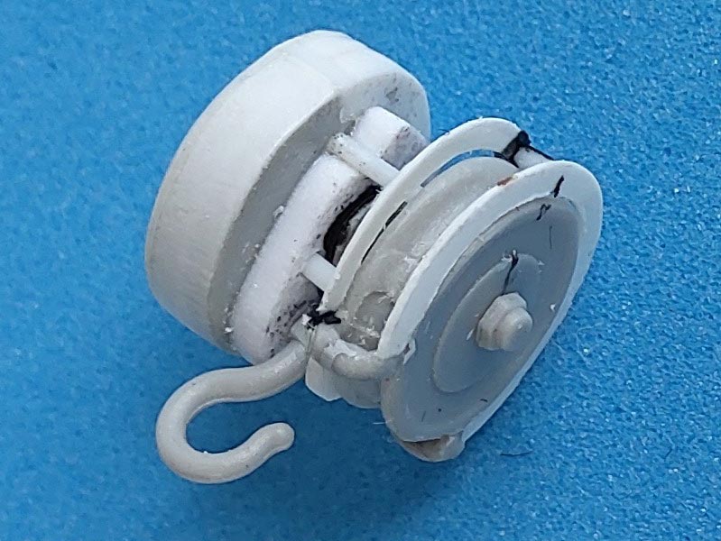 The chain hoist was another study in carelessness with facts and measurements on HB's side: Not only is the whole thing too small, but they also mixed up the diameters of the two components. F14/15 represent the wheel for the operating chain, and F 16/17 the reduction gear box. Now just as on your push bike, the driving wheel is the larger diameter one -- but not on the kit hoist. And the load chain should emanate right below the suspension hook, as otherwise the whole contraption would be canted into inoperability above a load. No wonder HB's instructions don't show where exactly they want the chains installed...
I opted against a total scratch build and "only" corrected the kit parts so they would look functional: The diameter difference was ignored, the gear box was made into a full circle with a domed addition plus a 1mm plate on its other side. The drive wheel had its "chain guard" representations sanded off and replaced with thin sheet styrene, a "geared" axle stub was set into its middle, and holes drilled for the support hook mounting rod. Both chains (different, as on the prototype) came from my spares.
 The shell arrester board fixing clamps F35 were whittled a little to look as if they might work. The kit's mounting grooves for the board supports PE4 had to be filled because they were at different heights (unlikely that different sorts of projos would be transported simultaneously) plus the PE is folded away from the walls so it can't be set into those grooves. Installing these supports all at the same height and with correct distances for their locks proved to be an exercise in measuring and testing --
 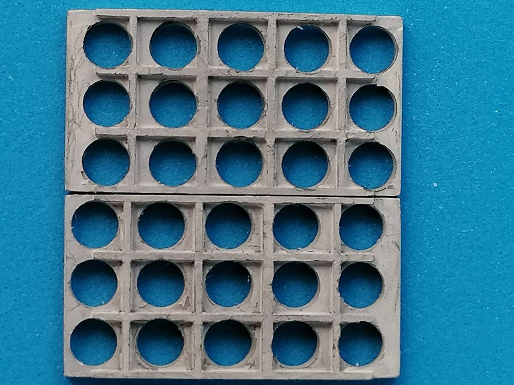 in hindsight, this should be done before cementing the box together! Another puzzling detail showed up in the arresting boards for the 155 mm ammo (F25,26): the distances from the outer rows of holes to the right and left sides are different. So, upper and lower boards should be mounted accordingly to avoid any projos standing at an (albeit slight) angle.
As for the tracks, I didn't want to go to any after market updates, as I find the kit's vinyl items absolutely sufficient. Their material has the right color for the rubber they represent, so all I painted was some rust on the end connectors and a little silver on the guide teeth's insides. The rest of the model received Revell Aqua 46 -- I hate painting, so don't expect more about that. The Ammo Box's inside, however, was painted white: unexpected, but documented in photos from before 1955. Markings will come when I decide what army to support with my model, and anyway, as I've stated elsewhere: I'm a builder, not a painter!
| Conclusion |
A kit that looks the part from a distance, but presents lots of correcting and detailing possibilities
| Preis / Leistung: | ***** | Paßgenauigkeit: | ***** |
| Detaillierung: | ***** | Schwierigkeitsstufe: | ***** |
 |
 |
 |
 |
 |
 |
 |
 |
 |
 |
 |
 |
 |
 |
 |
References:
- https://www.wk1963.at/m4_highspeedtractor_hkfw/hBA8D4A4C#hba8d4a6b
- https://www.wk1963.at/m4_hst
- https://books.google.de/books?id=QsMIAQAAIAAJ&pg=PA174&lpg=PA174&dq=TM+9-785&source=bl&ots=-qBr4a0WCQ&sig=ACfU3U1jFLxEhfjgdRdv0oqbsK6Q8oCyGQ&hl=de&sa=X&ved=2ahUKEwig49Do7szrAhUB6aQKHRT7COs4PBDoATAHegQIChAB#v=onepage&q=TM%209-785&f=false
- http://www.toadmanstankpictures.com/m4_hst.htm
- http://www.primeportal.net/apc/robert_de_craecker2/m4_18_ton_hst/
- https://www.eduard.com/out/media/36072.pdf
© 04/2022 Peter Schweisthal
5330 readers of this report since 29.04.2022